


10
to use in conjunction with a high-
pass filtered input signal to create a
bandpass crossover (for a midrange
or midbass driver). Set the switch to
H (high) to activate the high-pass
filter for use with satellite speakers or
tweeters on an amplifier group.
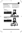
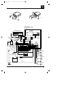
13. Mode Switches – These switches are
used to set the input mode for both
preamp and speaker-level inputs.
Set the switch to ST(ereo) for normal
operation on the group using
individual left and right inputs. Set
this switch to L to drive both the left
and right outputs with only a single
input on the left jack. Set the switch
to L+R to sum the left and right
inputs for a mono output on the
group. These switches do not affect
the preamp outputs.
14. Bass EQ Switch – These switches
activate a built-in Bass Boost circuit
used to increase low-bass output on
the selected group. These switches
do not effect the preamp outputs.
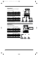
15. Group 2 Input Switch – This switch is
used to select which inputs will drive
Group 2 of the amplifier. Put the
switch in position “GR 1” to allow
Group 2 to be driven by the Group 1
inputs. Put the switch in the “GR 2”
position to drive Group 2 with the
Group 2 inputs.
16. Group 3 Input Switch – This switch is
used to select which inputs will drive
Group 3 of the amplifier. Put the
switch in position “GR 3” to allow
Group 3 to be driven by the Group 3
inputs. Put the switch in the “GR 2”
position to drive Group 3 with the
Group 2 inputs. Put this switch in the
“GR 1+2” position to drive Group 3
with the sum of Group 1 and 2 for a
non-fading subwoofer output on
Group 3.
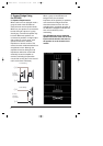
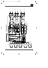
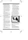
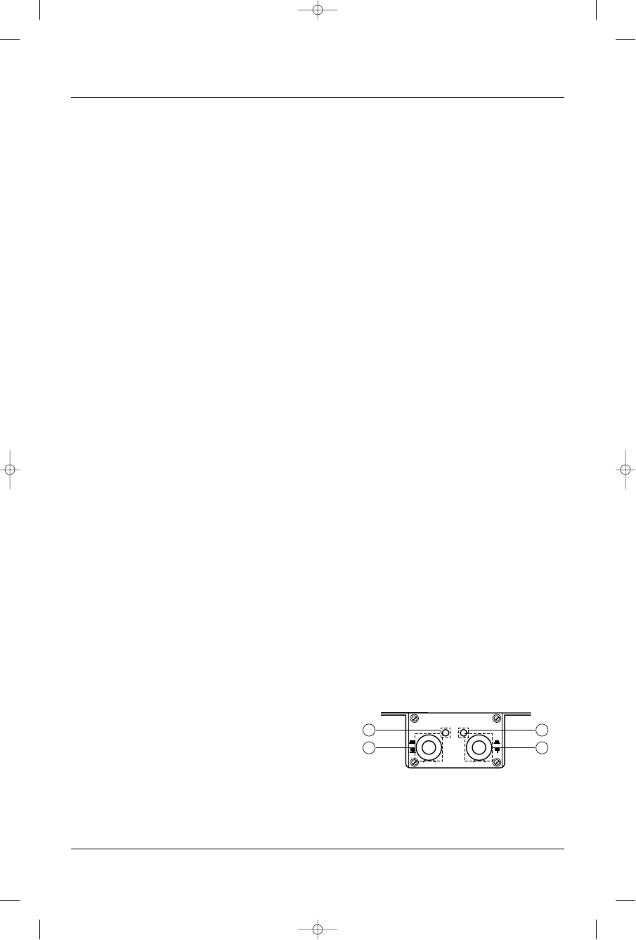
17. Remote Bypass/On Indicator – This
indicator is on when the Imaging
Enhancer is engaged and off when
the Imaging Enhancer is bypassed.
18. Driver/All Optimizer Indicator – This
indicator is on when the Virtual Center
Channel circuitry is in “Driver” opti-
mization mode and off when it is in
the “All” passenger mode. Note: The
enhancer on indicator must be on
before driver’s mode can enabled.
19. Front Ambience Control and
On/Bypass Switch – Rotating this
control adjusts the amount of
ambience and front staging width
produced by the Imaging Enhancer.
Pulling the knob places the Imaging
Enhancer in “Bypass” mode.
Pushing in the knob places the
Imaging Enhancer in “On” mode.
20. Rear Ambience and Driver/All
Optimizer Control – Rotating this
knob controls the amount of rear-fill
ambience and the “room size” of the
acoustic environment when used in
a system with rear speakers. Pulling
the knob out places the Imaging
Enhancer in “All” passengers opti-
mization mode. Pushing the knob in
places the unit in “Driver” optimizati-
on mode. Best results at the driver’s
position will be achieved with the
control in the “Driver” setting.
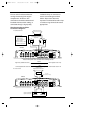
Power Indicator LED (on amp chassis
top) – LED steadily illuminates for normal
operation. LED blinks when protection
circuitry or muting is engaged.
19 20
17
18
MIN MAX
BYPASS
ENHANCER
ON
IMAGING ENHANCER
ENHANCER ON
DRIVER MODE
FRONT AMBIENCE REAR AMBIENCE
ALL
DRIVER
MIN MAX
GTH400-20107 06/03/98 15:49 Side 10