


12
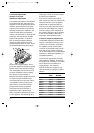
4.2 Internal Adjustments
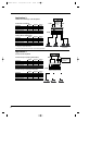
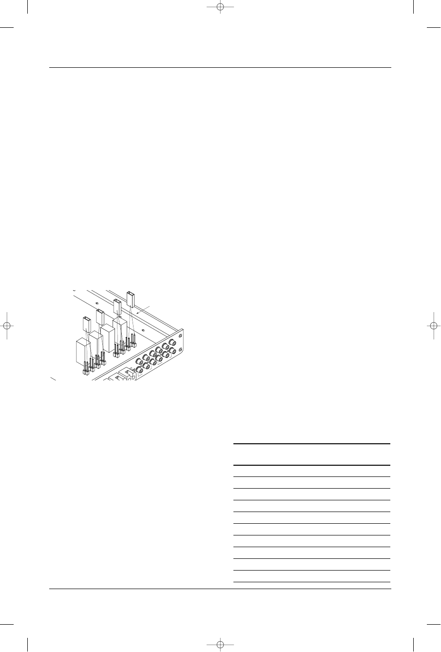
Speaker-Level Input
Impedance Adjustments
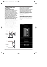
The speaker level inputs of the GTH400
come factory set with 100k ohm input
impedance. This will provide the lowest
distortion operation from the speaker
outputs of most modern head units by
reducing the power the amplifier in the
head unit must deliver to practically
nothing. On some older, or lower-priced
head units, this load will not facilitate
proper fader operation. To allow for
this, we have provided the ability to
change the input impedance of the
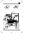
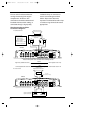
speaker-level inputs to 15 ohms. This is
accomplished by moving the jumpers
shown on the diagram above. This in-
put is also capable of directly accepting
signals, when in the 100k ohm setting,
from many Balanced Line Drivers such
as those sometimes used in competi-
tion vehicles. For best results, a
Balanced Line Driver capable of at least
4V nominal output should be used.
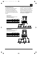
If the head unit has 4 channels of built-
in amplification and/or an electronic
fader control, you should leave the
jumpers in the factory set position.
If the head unit has 2 channels of
amplification, with a speaker-level
fader, the jumpers should be set to the
15-ohm position. This will always be a
rotary-type control, not one controlled
by electronic pushbuttons.
If you are not certain of the type of
fader control your unit has, measure the
resistance across one set of speaker
outputs with an ohmmeter (with the
head-unit off). Adjust the fader control
through its entire adjustment range. If
there is a change in the resistance as
the control is adjusted, set the jumpers
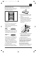
to the 15-ohm position. (See step 1,
page 16 to remove bottom cover.)
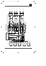
Crossover Frequency Adjustments
The GTH400 amplifiers include built-in
frequency selectable crossovers. One
crossover is connected in series with
the amplifier circuitry and the other
crossover is connected to the preamp
level output jacks. These crossovers
can be set in either the F (full bandwidth
operation), L (subwoofer operation), or
H (satellite operation).
The crossover frequencies are set by
chips inside the amplifier. These chips
are simply a set of resistors, connected
across the pins and molded into a
single package. The crossover
frequencies may be changed to any
value desired by changing the resistor
network.
Frequency Resistor JBL Part
Value Number
50Hz 47k Ω 1-23-750
80Hz 33k Ω 1-23-817
120Hz 22k Ω 1-23-820
200Hz 12k Ω 1-23-821
250Hz 10k Ω 1-23-810
375Hz 6.8k Ω 1-23-822
500Hz 4.7k Ω 1-23-815
650Hz 3.9k Ω 1-23-823
2.5kHz 1k Ω 1-23-824
5kHz 470 Ω 1-23-816
150HMS
100K
150HMS
100K
SPEAKER
INPUT
IMPEDANCE
SELECTOR
LINE INPUT
PREAMP OUT
150HMS
100K
150HMS
100K
JUMPER SELECTOR
SELECT 100K OR 15 OHMS
GTH400-20107 06/03/98 15:49 Side 12