


2 JL Audio
3
PLANNING YOUR INSTALLATION
It is important that you take the time to read
this manual and that you plan out your
installation carefully. The following are some
considerations that you must take into account
when planning your installation.
Cooling Efficiency Considerations:
The outer shell of your JL Audio amplifier is
designed to remove heat from the amplifier
circuitry. For optimum cooling performance, this
outer shell should be exposed to as large a volume
of air as possible. Enclosing the amplifier in a
small, poorly ventilated chamber can lead to
excessive heat build-up and degraded
performance. If an installation calls for an
enclosure around the amplifier, we recommend
that this enclosure be ventilated with the aid
of a fan. In normal applications, fan-cooling
is not necessary.
Mounting the amplifier upside down is
strongly discouraged.
If mounting the amplifier under a seat,
make sure there is at least 1 inch (2.5 cm) of
space above the amplifier’s outer shell to permit
proper cooling.
Safety Considerations:
Your amplifier needs to be installed in a dry,
well-ventilated environment and in a manner
which does not interfere with your vehicle’s safety
equipment (air bags, seat belt systems, ABS brake
systems, etc.). You should also take the time to
securely mount the amplifier so that it does not
come loose in the event of a collision or a sudden
jolt to the vehicle.
Stupid Mistakes to Avoid
• Check before drilling any holes in your vehicle
to make sure that you will not be drilling
through a gas tank, brake line, wiring harness or
other vital vehicle system.
• Do not run system wiring outside or underneath
the vehicle. This is an extremely dangerous
practice which can result in severe damage to
your vehicle and person.
• Protect all system wires from sharp metal
edges and wear by carefully routing them,
tying them down and using grommets and
loom where appropriate.
• Do not mount the amplifier in the engine
compartment, under the vehicle, on the roof
or in any other area that will expose the
amplifier circuitry to the elements.
PROTECT YOUR HEARING!
We value you as a long-term customer. For
that reason, we urge you to practice restraint in
the operation of this product so as not to damage
your hearing and that of others in your vehicle.
Studies have shown that continuous exposure to
high sound pressure levels can lead to permanent
(irreparable) hearing loss. This and all other
high-power amplifiers are capable of producing
such high sound pressure levels when connected
to a speaker system. Please limit your continuous
exposure to high volume levels.
While driving, operate your audio system in
a manner that still allows you to hear necessary
noises to operate your vehicle safely (horns,
sirens, etc.).
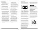
SERIAL NUMBER
In the event that your amplifier requires
service or is ever stolen, you will need to have
a record of the product’s serial number. Please
take the time to enter that number in the space
provided below. The serial number can be found
on the bottom panel of the amplifier and on the
amplifier packaging.
Serial Number:
INSTALLATION APPLICATIONS
This amplifier is designed for operation in
vehicles with 12 volt, negative-ground electrical
systems. Use of this product in vehicles with
positive ground and/or voltages other than 12V
may result in damage to the product and will void
the warranty.
This product is not certified or approved for
use in aircraft.
Do not attempt to “bridge” the outputs of this
amplifier with the outputs of a second amplifier,
including an identical one.
HP
|
Off
|
LP
Filter Mode
High-PassLow-Pass
Filter Frequency (Hz)
Filter Frequency (Hz)
Input Sens.
Input Sens.
CH 3&4
Input From
min maxmin max 60 1.2k
High-Pass
60 1.2k 40 150
Low-Pass
40 150
Off +12dB
High-Level InputsHigh-Level Inputs
Bass Boost
HP
|
Off
|
LP
Filter Mode
1&2
|
3&4
Off +12dB
Bass Boost
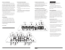
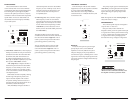
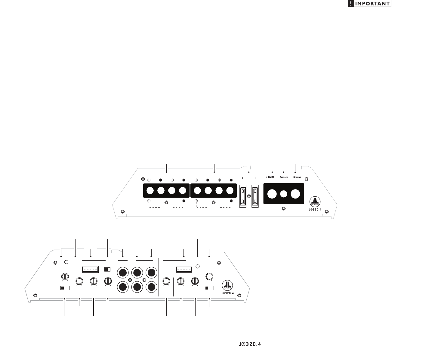
Channel 3 & 4 Controls
CH 1 (Left) CH 3 (Left)
Protect
Channel 1 & 2 Controls
Power
CH 2 (Right)
LEFT
RIGHT CH 4 (Right)
Pre-Outs Amplifier Inputs
Protection Status
Indicator
(pg. 11)
Low-Pass Filter
Frequency Control
(pg. 8)
Input Sensitivity
Control
(pg. 7)
Input Sensitivity
Control
(pg. 7)
Filter Mode
Selector
(pg. 8)
Filter Mode
Selector
(pg. 8)
Channel Input
Selector
(pg. 7)
Left & Right
Preamp Output Jacks
(pg. 9)
High-Level
Input Jack
(pg. 6,7)
Power Status
Indicator
(pg. 11)
Bass Boost
Control
(pg. 9)
Bass Boost
Control
(pg. 9)
High Level
Input Jack
(pg. 6,7)
High-Pass Filter
Frequency Control
(pg. 8)
High-Pass Filter
Frequency Control
(pg. 8)
Low-Pass Filter
Frequency Control
(pg. 8)
CH 1 & CH 2
Preamp Input Jacks
(pg. 6)
CH 3 & CH 4
Preamp Input Jacks
(pg. 6)
Remote Turn-On
Connector
(pg. 6)
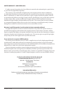
CH 1 & CH 2
Speaker Outputs
(pg. 9)
CH 3 & CH 4
Speaker Outputs
(pg. 9)
+12 V Power
Connector
(pg. 5)
Fuses
(pg. 5)
Chassis Ground
Connector
(pg. 5)
Made in China
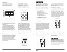
CHANNEL 1 (L) CHANNEL 2 (R)
Bridged Bridged
CHANNEL 3 (L) CHANNEL 4 (R) FUSES
30A30A