


8 JL Audio
9
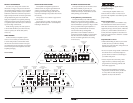
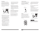
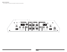
“BASS BOOST” CONTROLS
Each channel pair of the J2-320.4 includes a
single band, boost-only bass equalizer controlled
by a rotary knob marked “Bass Boost”.
This control has a boost range of 0dB (full-
counterclockwise) to +12dB (full-clockwise) and
is centered at 45 Hz.
HP
|
Off
|
LP
Filter Mode
High-PassLow-Pass
Filter Frequency (Hz)
Filter Frequency (Hz)
Input Sens.
Input Sens.
CH 3&4
Input From
min maxmin max 60 1. 2k
High-Pass
60 1. 2k 40 15 0
Low-Pass
40 15 0
Off +12dB
High-Level InputsHigh-Level Inputs
Bass Boost
HP
|
Off
|
LP
Filter Mode
1&2
|
3&4
Off +12dB
Bass Boost
Channel 3 & 4 Controls
CH 1 (Left) CH 3 (Left)
Protect
Channel 1 & 2 Controls
Power
CH 2 (Right)
LEFT
RIGHT CH 4 (Right)
Pre-Outs Amplifier Inputs
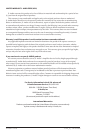
PREOUTS
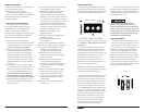
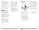
The J2-320.4 incorporates a pass-through
preamp output section, so that additional
amplifiers can be easily added to the system.
This pass-through pre-amp output delivers a
summed stereo signal , combining the Ch 1 and 3
signals into a Left Preamp Output Signal and the
Ch. 2 and 4 signals into a Right Channel Preamp
Output signal.
HP
|
Off
|
LP
Filter Mode
High-PassLow-Pass
Filter Frequency (Hz)
Filter Frequency (Hz)
Input Sens.
Input Sens.
CH 3&4
Input From
min maxmin max 60 1. 2k
High-Pass
60 1. 2k 40 15 0
Low-Pass
40 15 0
Off +12dB
High-Level InputsHigh-Level Inputs
Bass Boost
HP
|
Off
|
LP
Filter Mode
1&2
|
3&4
Off +12dB
Bass Boost
Channel 3 & 4 Controls
CH 1 (Left) CH 3 (Left)
Protect
Channel 1 & 2 Controls
Power
CH 2 (Right)
LEFT
RIGHT CH 4 (Right)
Pre-Outs Amplifier Inputs
The preamp output signal is not affected by the
“Bass Boost” processing selected for the amplifier
or by any crossover filter selected (if the input
signal is full-range, the preamp output will be
full-range).
Note: The signal level of the “Preamp Output” is
always line-level (low voltage).
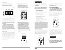
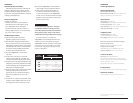
SPEAKER OUTPUTS
The J2-320.4’s speaker outputs are designed to
accept 16 AWG - 8 AWG wire.
Each pair of the J2-320.4’s channels are
designed to deliver power into speaker loads equal
to or greater than 2 ohms per channel when using
a “stereo” configuration and speaker loads equal
to or greater than 4 ohms per bridged pair of
channels when using a “bridged” configuration.
HP
|
Off
|
LP
Filter Mode
High-PassLow-Pass
Filter Frequency (Hz)
Filter Frequency (Hz)
Input Sens.
Input Sens.
CH 3&4
Input From
min maxmin max 60 1. 2k
High-Pass
60 1. 2k 40 15 0
Low-Pass
40 15 0
Off +12dB
High-Level InputsHigh-Level Inputs
Bass Boost
HP
|
Off
|
LP
Filter Mode
1&2
|
3&4
Off +12dB
Bass Boost
Channel 3 & 4 Controls
CH 1 (Left) CH 3 (Left)
Protect
Channel 1 & 2 Controls
Power
CH 2 (Right)
LEFT
RIGHT CH 4 (Right)
Pre-Outs Amplifier Inputs
Speaker loads below 2 ohms nominal per
channel are not recommended and may cause
the amplifier to initiate a protection mode.
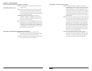
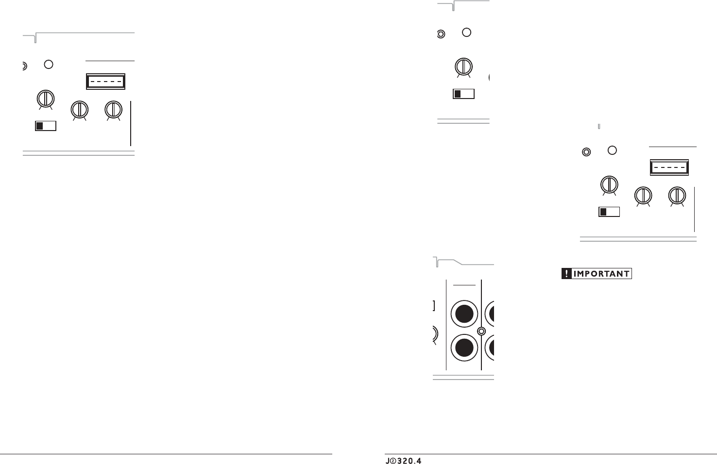
FILTER CONTROLS
The active filter built into each channel
section of the J2-320.4 can be used to eliminate
potentially harmful and/or undesired frequencies
from making their way through the amplifier
sections to the speaker(s). This serves to improve
tonal balance and to avoid distortion and possible
speaker failure. Correct use of these filters can
substantially increase the longevity and fidelity
of your audio system.
HP
|
Off
|
LP
Filter Mode
High-PassLow-Pass
Filter Frequency (Hz)
Filter Frequency (Hz)
Input Sens.
Input Sens.
CH 3&4
Input From
min maxmin max 60 1. 2k
High-Pass
60 1. 2k 40 15 0
Low-Pass
40 15 0
Off +12dB
High-Level InputsHigh-Level Inputs
Bass Boost
HP
|
Off
|
LP
Filter Mode
1&2
|
3&4
Off +12dB
Bass Boost
Channel 3 & 4 Controls
CH 1 (Left) CH 3 (Left)
Protect
Channel 1 & 2 Controls
Power
CH 2 (Right)
LEFT
RIGHT CH 4 (Right)
Pre-Outs Amplifier Inputs
1) “Filter Mode” Control: The J2-320.4 employs a
12dB per octave filter for each pair of channels
(one filter for channels 1&2 and another filter
for channels 3&4). Each of these filters can
be configured independently into one of two
filter types or defeated completely by way of the
three-position “Filter Mode” switches:
“HP” (High-Pass): Configures the filter to
attenuate frequencies below the selected filter
frequency at a rate of 12dB per octave. This is
useful for connection of component speakers
to one or both of the J2-320.4’s channel pairs in
a bi-amplified system.
Off”: Defeats the filter completely, allowing
the full range of frequencies present at the
inputs to feed the amplifier. This is useful
for systems utilizing outboard crossovers or
requiring full-range reproduction from one or
both of the J2-320.4’s channel pairs.
“LP” (Low-Pass): Configures the filter to
attenuate frequencies above the selected filter
frequency at a rate of 12dB per octave. This is
useful for connection of subwoofer(s) to one
or both of the J2-320.4’s channel pairs in a
bi-amplified system.
2) “Filter Freq. (Hz)” The J2-320.4 has separate
Filter Frequency controls in each Channel
Controls section for the low-pass filter and the
high-pass filter. You will only use one of these
in each channel section, depending on which
“Filter Mode” you have selected (or none of
them if you have selected the “Off” position for
the “Filter Mode”).
The High-Pass filters in the J2-320.4 are fully
variable between 60 Hz and 1.2 kHz (1200 Hz) via
the control knobs labeled “High-Pass”. The “8
o’clock” position corresponds to 80 Hz and is a
good starting point for system tuning.
The Low-Pass filters in the J2-320.4 are fully
variable between 40 Hz and 150 Hz via the
control knobs labeled “High-Pass”. The “12
o’clock” position corresponds to 80 Hz and is a
good starting point for system tuning.