


6 JL Audio
7
Make sure you observe correct polarity in
making the “High Level Input” connections.
Failure to do so will reduce bass and affect
stereo imaging.
The connections for the “High Level Inputs” plug
wires are as follows from left to right on the plug:
Channels 1&2 (FRONT)
White: Left Positive (+)
White/Black: Left Negative (–)
Black: Common Ground (rarely used)*
Gray: Right Positive (+)
Gray/Black: Right Negative (–)
Channels 3&4 (REAR or SUB)
Green: Left Positive (+)
Green/Black: Left Negative (–)
Black: Common Ground (rarely used)*
Purple: Right Positive (+)
Purple/Black: Right Negative (–)
*The only time you will use the Common Ground
connections is with some older (pre-1980’s) factory
systems or head units that ground their speakers to
chassis ground. To use these connections, ground
the black wires on the plugs to chassis ground and
only connect the Left and Right Positive plug wires
to the factory radio outputs.
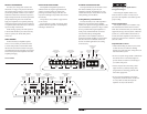
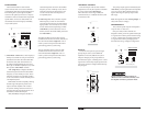
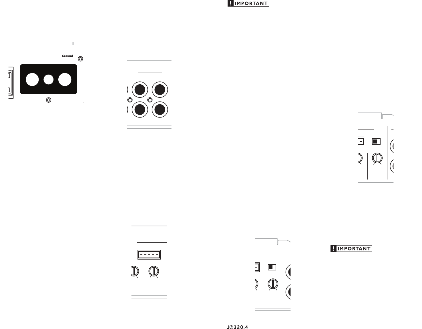
“CH 3&4 Input From” Switch
If you wish to send four discrete channels of
input into the J2-320.4, simply use all four inputs
(Channels 1 & 2 and Channels 3 & 4) and set the
“CH 3&4 Input From” switch to “3&4”.
HP
|
Off
|
LP
Filter Mode
High-PassLow-Pass
Filter Frequency (Hz)
Filter Frequency (Hz)
Input Sens.
Input Sens.
CH 3&4
Input From
min maxmin max 60 1. 2k
High-Pass
60 1. 2k 40 15 0
Low-Pass
40 15 0
Off +12dB
High-Level InputsHigh-Level Inputs
Bass Boost
HP
|
Off
|
LP
Filter Mode
1&2
|
3&4
Off +12dB
Bass Boost
Channel 3 & 4 Controls
CH 1 (Left) CH 3 (Left)
Protect
Channel 1 & 2 Controls
Power
CH 2 (Right)
LEFT
RIGHT CH 4 (Right)
Pre-Outs Amplifier Inputs
If you wish to feed all four channels by using
only two channels of input, set the “CH 3&4
Input From” switch to “1&2” and use only the
inputs to channels 1 & 2.
INPUT SENSITIVITY CONTROLS
The controls labeled “Input Sens.” located in
each “Channel Controls” section can be used
to match the source unit’s output voltage to the
input stage of each pair of amplifier channels
for maximum clean output. Rotating the control
clockwise will result in higher sensitivity (louder
for a given input voltage). Rotating the control
counter-clockwise will result in lower sensitivity
(quieter for a given input voltage.)
HP
|
Off
|
LP
Filter Mode
High-PassLow-Pass
Filter Frequency (Hz)
Filter Frequency (Hz)
Input Sens.
Input Sens.
CH 3&4
Input From
min maxmin max 60 1. 2k
High-Pass
60 1. 2k 40 15 0
Low-Pass
40 15 0
Off +12dB
High-Level InputsHigh-Level Inputs
Bass Boost
HP
|
Off
|
LP
Filter Mode
1&2
|
3&4
Off +12dB
Bass Boost
Channel 3 & 4 Controls
CH 1 (Left) CH 3 (Left)
Protect
Channel 1 & 2 Controls
Power
CH 2 (Right)
LEFT
RIGHT CH 4 (Right)
Pre-Outs Amplifier Inputs
To properly set the amplifier for maximum
clean output, please refer to Appendix A (page
12) in this manual. After using this procedure,
you can then adjust any or all “Input Sens.”
levels downward if this is required to achieve the
desired system balance.
Do not increase any “Input Sens.” setting for
any channel(s) of any amplifier in the system
beyond the maximum level established during
the procedure outlined in Appendix A (page
12). Doing so will result in audible distortion
and possible speaker damage.
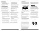
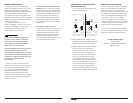
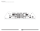
TURNON LEAD
The J2-320.4 is turned on and off
using a conventional +12V remote turn-
on lead, typically controlled by the
source unit’s remote turn-on output.
Made in China
CHANNEL 1 (L) CHANNEL 2 (R)
Bridged Bridged
CHANNEL 3 (L) CHANNEL 4 (R) FUSES + VDC
30A30A
Remote
The amplifier will turn on when +12V is
present at its “Remote” input and turn off when
+12V is switched off. If a source unit does not
have a dedicated remote turn-on output, the
amplifier’s turn-on lead can be connected to +12V
via a switch that derives power from an ignition-
switched circuit.
18 AWG wire is more than adequate for
the remote turn-on connection. To connect
the remote turn-on wire to the amplifier, strip
1/2-inch (12 mm) of insulation from the wire
and insert it into the “Remote” receptacle on the
power connector. Tighten the connector down
using a Phillips screwdriver.
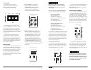
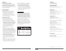
INPUT SECTIONS
The J2-320.4’s has two input sections: one for
Channels 1&2 and another for Channels 3&4.
These input sections allows you to send signals to
the amplifier sections through the use of either
two or four inputs. Each input section offers
two input connection methods, one for high-
level (speaker level) signals and one for low-level
(preamp level) signals.
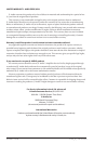
1) Low-Level Inputs: A standard left/
right pair of RCA type jacks in the
“Amplifier Inputs” section is used for
preamp level (low-level) signal input
on the J2-320.4. This is the preferred
connection method whenever available.
HP
|
Off
|
LP
Filter Mode
High-PassLow-Pass
Filter Frequency (Hz)
Filter Frequency (Hz)
Input Sens.
Input Sens.
CH 3&4
Input From
min maxmin max 60 1. 2k
High-Pass
60 1. 2k 40 15 0
Low-Pass
40 15 0
Off +12dB
High-Level InputsHigh-Level Inputs
Bass Boost
HP
|
Off
|
LP
Filter Mode
1&2
|
3&4
Off +12dB
Bass Boost
Channel 3 & 4 Controls
CH 1 (Left) CH 3 (Left)
Protect
Channel 1 & 2 Controls
Power
CH 2 (Right)
LEFT
RIGHT CH 4 (Right)
Pre-Outs Amplifier Inputs
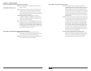
2) High-Level Inputs: If your system does
not offer a preamp level signal option, you
can connect speaker level signals directly to
the “High-Level Inputs” connectors using
the supplied mating connectors and wire
harnesses. Simply splice the appropriate
left/right and positive/negative wires to the
included harnesses and plug the harness into
the “High-Level Inputs” connectors on the
amplifier. The J2-320.4 will attenuate the high-
level signals to make them compatible with its
input stages.
HP
|
Off
|
LP
Filter Mode
High-PassLow-Pass
Filter Frequency (Hz)
Filter Frequency (Hz)
Input Sens.
Input Sens.
CH 3&4
Input From
min maxmin max 60 1. 2k
High-Pass
60 1. 2k 40 15 0
Low-Pass
40 15 0
Off +12dB
High-Level InputsHigh-Level Inputs
Bass Boost
HP
|
Off
|
LP
Filter Mode
1&2
|
3&4
Off +12dB
Bass Boost
Channel 3 & 4 Controls
CH 1 (Left) CH 3 (Left)
Protect
Channel 1 & 2 Controls
Power
CH 2 (Right)
LEFT
RIGHT CH 4 (Right)
Pre-Outs Amplifier Inputs