


10 JL Audio
11
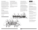
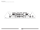
AMPLIFIER STATUS INDICATOR LIGHTS &
PROTECTION CIRCUITRY
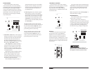
There are two status indicator lights on the
control panel of the amplifier.
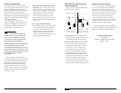
HP
|
Off
|
LP
Filter Mode
High-PassLow-Pass
Filter Frequency (Hz)
Filter Frequency (Hz)
Input Sens.
Input Sens.
CH 3&4
Input From
min maxmin max 60 1. 2k
High-Pass
60 1. 2k 40 15 0
Low-Pass
40 15 0
Off +12dB
High-Level InputsHigh-Level Inputs
Bass Boost
HP
|
Off
|
LP
Filter Mode
1&2
|
3&4
Off +12dB
Bass Boost
Channel 3 & 4 Controls
CH 1 (Left) CH 3 (Left)
Protect
Channel 1 & 2 Controls
Power
CH 2 (Right)
LEFT
RIGHT CH 4 (Right)
Pre-Outs Amplifier Inputs
HP
|
Off
|
LP
Filter Mode
High-PassLow-Pass
Filter Frequency (Hz)
Filter Frequency (Hz)
Input Sens.
Input Sens.
CH 3&4
Input From
min maxmin max 60 1. 2k
High-Pass
60 1. 2k 40 15 0
Low-Pass
40 15 0
Off +12dB
High-Level InputsHigh-Level Inputs
Bass Boost
HP
|
Off
|
LP
Filter Mode
1&2
|
3&4
Off +12dB
Bass Boost
Channel 3 & 4 Controls
CH 1 (Left) CH 3 (Left)
Protect
Channel 1 & 2 Controls
Power
CH 2 (Right)
LEFT
RIGHT CH 4 (Right)
Pre-Outs Amplifier Inputs
1) “Power” (Green): lights to indicate that the
amplifier is turned on and operating normally.
Located at the far left of the control panel.
2) “Protect” (Red): Indicates that the amplifier
protection circuitry has been activated
to prevent product failure due to thermal
overload, short-circuit or a dangerously
low impedance connected to the amplifier
outputs. Connecting the speaker outputs
to an impedance lower than 2 ohms stereo
(4 ohms bridged) will cause this protection
mode to activate. When this protection mode
is activated, the amplifier will shut down to
protect its circuitry. When the problem is
corrected, the amplifier will return to normal
operation and the “Protect” LED will shut off.
SERVICING YOUR TMA AMPLIFIER
If your amplifier fails or malfunctions, please
return it to your authorized JL Audio dealer so
that it may be sent in to JL Audio for service.
There are no user serviceable parts or fuses inside
the amplifier. The unique nature of the circuitry
in the JL Audio amplifiers requires specifically
trained service personnel. Do not attempt
to service the amplifier yourself or through
unauthorized repair facilities. This will not only
void the warranty, but may result in the creation
of more problems within the amplifier.
If you have any questions about the installation
or setup of the amplifier not covered in this manual,
please contact your dealer or technical support.
JL Audio Technical Support:
(9 5 4) 4 43 -110 0
9:00 AM – 5:30 PM (Eastern Time Zone)
Monday - Friday
BRIDGING CONSIDERATIONS
Bridging is the practice of combining the
output of two amplifier channels to drive a single
load. When bridged, each channel produces
signals of equal magnitude, but opposite polarity.
The combined output of the two channels
provides twice the output voltage available from a
single channel. The J2-320.4 has been designed for
bridging of its channel pairs without the need for
input inversion adaptors.
To bridge a pair of channels, use the
“Left +” and “Right –” speaker connectors only
(the “Left –” and “Right +” remain unused).
When bridged, each channel will deliver
optimum power into a 4 ohm load.
When a pair of channels are bridged, they
will deliver 160W x 1 into a 4 ohm load or
120W x 1 into an 8 ohm load. Operating a
pair of bridged channels into a load lower
than 4 ohms is not recommended.
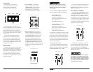
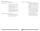
Because a bridged pair of channels requires that
both channels receive input, you need to
connect both left and right inputs to the source
unit. Connection of only one input will result in
reduced power output, increased distortion and
can cause the amplifier to overheat.
Do not do this!
When a pair of the J2-320.4’s channels are
operating in bridged mode, the output will be in
mono (only one channel). This mono channel
can contain right channel only information,
left channel only information or the sum of
the information from both the right and left
channels. In order to achieve one of these options,
configure the inputs to that pair of channels in
one of these two ways:
1) Left Channel Only or Right Channel Only
Information: If you wish to send a left-only
or right-only signal to a pair of the J2-320.4’s
channels, use a “Y-Adaptor” to split the single
channel signal into both left and right RCA
inputs. This option is useful when using a
pair of the J2-320.4’s channels to drive left
channel speakers only and the other pair of
the J2-320.4’s channels to drive right channel
speakers only.
2) Left + Right Channel Information:
When bridged and fed by a stereo input, a pair
of the J2-320.4’s channels will automatically
combine the left and right channels into a
summed mono (left + right) channel. This
option is useful when using a pair of the
J2-320.4’s channels to drive a subwoofer system
or a summed mono center channel.