


Continued on Next Page
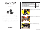
SLPK-CAN-SPYDER1_INSTR_SKU# 011312
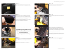
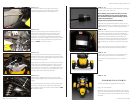
S T E P 1 5
Install the 3/8-16 x 1-1/4” Hex Head Bolt through the included
Split Lock Washer, the 1-1/4” Fender Washer and the hole
drilled in STEP 14 into the enclosure, tighten this fastener
down.
Once this fastener is tight, the front air dam can be re-
installed.
S T E P 1 4
Drill a 5/16” hole where the indentation was made in STEP 13.
Before drilling, always make sure that you are not
going to be drilling into any gas lines, brake lines,
tires, transmission lines, electrical wiring, exhaust
systems or anything else that might cause a
reduction in your weekly pay.
Always wear eye protection when drilling!
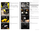
S T E P 1 3
Thread the 3/8-16 x 1-1/4” Hex Head Bolt all the way into
the enclosure. Press the enclosure down into the storage
compartment towards the right front corner, the Hex Head
Bolt will leave an indentation in the wax square.
Once you’ve confirmed the indentation in the wax square,
remove the Hex Head Bolt from the enclosure.
S T E P 1 2
Looking down and towards the front right corner of the
storage compartment, position the wax square as shown.
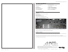
Page 3 • JL Audio, Inc 2009
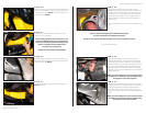
S T E P 1 7
Put a length of masking tape as shown on each side of the
top fairing.
S T E P 1 9
Align pod with the back edge matching the fairing (as
shown) and the front corners as show in
STEP 20.
S T E P 1 8
Remove the larger speaker from each pod, the smaller
speaker can remain in the pod. The speakers are only
secured in the pods for shipping with 3- screws, use all six
when re-installing. (In the following pictures, both speakers
have been removed, this is NOT necessary!)
Position foam strips as shown on each pod.
Note the location of the three holes in the pods, two will be
used to mount the pod, the third will be the wire run.
S T E P 1 6
Remove gauge cluster as shown by lifting top panel then
depressing two locking tabs on top of the cluster.