


Continued on Next Page
SLPK-CAN-SPYDER1_INSTR_SKU# 011312
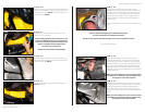
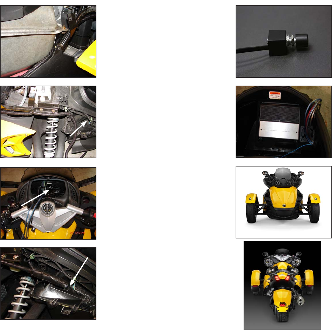
S T E P 3 0
Again, secure all cables along the full run to ensure that
they cannot get tangled in any moving parts or the exhaust
system.
The signal and speaker wires will join with the power cables
that came up the side of the motorcycle and all enter the
front storage compartment through the hole drilled in STEP
8, as shown by arrow.
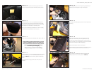
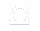
S T E P 2 9
From the gauge cluster location, there should be the two
speaker wires, the wire for the Remote Level Control (it looks
like a phone cord), the small gauge blue remote turn on wire
(included) and the signal cable.
Many people find it easier to run the mini plug on the signal
cable up from the amplifier location than running the rca’s
on the amplifier end of that cable down. If you choose to
run that cable up, run a “pull line” or, string along with it, that
way, once the run is made, you can use the pull line to pull
the other cables down towards the amplifier.
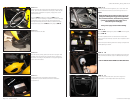
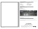
S T E P 2 8
Make sure that the cabling is secured so that there is no
way that it can get tangled in any moving parts on the
motorcycle, including steering, suspension, exhaust or
passengers. The cable will be joined by the speaker wire,
signal wire for the RLC and signal from the source, just before
it enters the front storage compartment (through the hole
drilled in
STEP 8, as shown by arrow.)
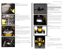
S T E P 2 7
Run the power cables up the right hand side of the
motorcycle, securing it as described earlier at regular
intervals alongside the frame or other cable runs.
Page 5 • JL Audio, Inc 2009
S T E P 3 2
Follow the included instructions for installing the XD400/4,
the small blue wire that was run down from the Gauge
cluster area needs to be spliced in to a accessory switched
power source so that the amplifier turns off when the
motorcycle is turned off. If the amplifier remains on when
the motorcycle is turned off, there is strong potential for
battery drainage! All connections should be made at this
time.
After all connections are made, review the schematic on
page 6, make sure that all wires are where they belong.
S T E P 3 4
C O N G R A T U L A T I O N S !
You have completed the installation for this model!
Enjoy your new Slampak®!
Please refer to the Power Recommendation section for sug-
gestions on basic amplifier set-up help. For further details on
the amplifier, please reference the amplifier owners manual
(included).
S T E P 3 3
Double check all connections, once everything has been
confirmed as good, install the fuse near the battery.
Re-install all removed bodywork, don’t miss any of the
hardware.
S T E P 3 1
To mount the Remote level control, determine a convenient
and safe location, drill a 3/8” hole,
Before drilling, always make sure that you are not
going to be drilling into any gas lines, brake lines,
tires, transmission lines, electrical wiring, exhaust
systems or anything else.
Always wear eye protection when drilling!
Gently but firmly, pull the knob off of the control, use the
supplied washers and nut to “sandwich” the surface you just
drilled the hole in, mount the control, replace the knob.