


(No.49793)1-41
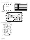
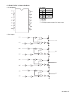
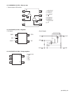
• Pin function
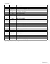
Pin No. Symbol Function
1 VIN1-A CH1 input AMP_inverted input
2 VIN1+A CH1 input AMP_non-inverted input
3 VCCP1 CH1 and CH2 power stage power supply
4 VO1+ Output pin(+)for channel 1
5 VO1- CH1 output pin (-) for channel 1
6 VO2+ Output pin(+)for channel 2
7 VO2- Output pin(-)for channel 2
8 VO3+ Output pin(+)for channel 3
9 VO3- Output pin(-)for channel 3
10 VO4+ Output pin(+)for channel 4
11 VO4- Output pin(-)for channel 4
12 VCCP2 CH3 and CH4 power stage powr supply
13 VIN4 Input pin for channel 4
14 VIN4G Input pin for channel 4(for gain adjustment)
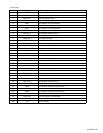
15 VIN3 Input pin for channel 3
16 VIN3G Input pin for channel 3(for gain adjustment)
17 VIN2 Input pin for channel 2
18 VIN2G Input pin for channel 2(for gain adjustment)
19 REGIN External PNP transistor base connection
20 3.3VREG 3.3VREG output pin external PNP transistor,collector connection
21 VCCS Signal system GND
22 VREFIN Reference voltage application pin
23 MUTE Output ON/OFF pin
24 VIN1_SW CH1 input OP AMP_changeover pin
25 S_GND Signal system GND
26 VIN1+B CH1 AMP_B non-inverted input pin
27 VIN1-B CH1 AMP_B inverted input pin
28 VIN1 CH1 input pin input OP_AMP output pin