


(No.49793)1-43
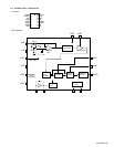
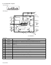
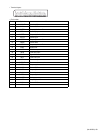
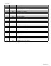
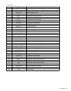
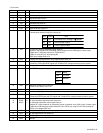
• Pin function
Pin No. Symbol Function
1 REF IC signal GND
2 DEFP IN 1 Ope amp positive input
3 DEFN IN 1 Ope amp negative input
4 INA 1 Input selector ch1 input terminal
5 INB 1 Input selector ch1 input terminal
6 INC 1 Input selector ch1 input terminal
7 IND 1 Input selector ch1 input terminal
8 DEFN OUT 1 Operation outoutterminal (-)
9 SEL OUT 1 Input selector output terminal
10 VOL IN 1 Volume 1 input terminal
11 TONE OUT 1 Tone output terminal
12 FADER IN 1 Volume 2 input terminal
13 REAR OUT1 Fader volume (rear) output terminal
14 FRONT OUT 1 Fader volume (front) output terminal
15 NonFadaer OUT 1 Non fader volume output terminal
16 GND GND
17 DATA Control data input terminal
18 VDDOUT 1 Connect to GND with capacitor
19 VDDOUT 2 Connect to GND with capacitor
20 CLOCK Serial data clock input terminal
21 VDD VDD for digital
22 NonFadaer OUT 2 Non fader volume output terminal
23 FRONT OUT 2 Fader volume (front) output terminal
24 REAR OUT2 Fader volume (rear) output terminal
25 FADER IN 2 Volume 2 input terminal
26 TONE OUT 2 Tone output terminal
27 VOL IN 2 Volume 1 input terminal
28 SEL OUT 2 Input selector output terminal
29 DEFN OUT 2 Ope amp output terminal (-)
30 IND 2 Input selector switch ch2 input terminal
31 INC 2 Input selector switch ch2 input terminal
32 INB 2 Input selector switch ch2 input terminal
33 INA 2 Input selector switch ch2 input terminal
34 DEFN IN 2 Ope amp negative input terminal
35 IEFP IN 2 Ope amp positive input terminal
36 VCC VCC for analog