


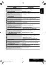
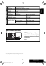
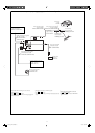

(ILLUMINATION)
(REMOTE OUT)
(POWER ANTENNA)
(PARKING BRAKE)
(TEL MUTING)
REVERSE
GEAR
SIGNAL
3
2
1
3
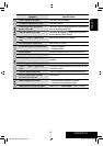
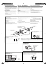
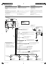
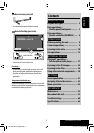
ELECTRICAL CONNECTIONS
To prevent short circuits, we recommend that you disconnect the
battery’s negative terminal and make all electrical connections before
installing the unit.
• Be sure to ground this unit to the car’s chassis again after
installation.
Before connecting
: Check the wiring in the vehicle carefully.
Incorrect connection may cause serious damage to this unit.
The leads of the power cord and those of the connector from the car
body may be different in color.
1 Connect the colored leads of the power cord in the order specified
in the illustration below.
2 Connect the antenna cord.
3 Finally connect the wiring harness to the unit.
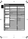
15 A fuse
15 A ۘᎳീ
øî«Ï¢π“¥ 15 A
Rear ground terminal
ʹጅ݈ࠌϙၷʪ
®ÿ¥‡™◊ËÕ¡µËÕ“¬¥‘π¥È“πÀ≈—ß
*
1
Not included for this unit
*
1
ʿᎲʹጅಏա
*
1
‰¡Ë‰¥È„ÀÈ¡“°—∫™ÿ¥ª√–°Õ∫π’È
Ignition switch
ᓭ̑ළᘕ
«‘∑™Ï®ÿ¥√–‡∫‘¥
Fuse block
ۘᎳീవ˔
·ºßøî«
White with black stripe
ΎиઘЉ෨иঙ
’¢“«·∂∫¥”
White
Ύи
’¢“«
Gray with black stripe
НиઘЉ෨иঙ
’‡∑“·∂∫¥”
Gray
Ни
’‡∑“
Green with black stripe
ႋиઘЉ෨иঙ
’‡¢’¬«·∂∫¥”
Green
ႋи
’‡¢’¬«
Purple with black stripe
ാиઘЉ෨иঙ
’¡Ë«ß·∂∫¥”
Purple
ാи
’¡Ë«ß
Left speaker (front)
ͣಙᑵ(ۮ)
≈”‚æß´È“¬ (ÀπÈ“)
Right speaker (front)
͆ಙᑵ(ۮ)
≈”‚æߢ«“ (ÀπÈ“)
Left speaker (rear)
ͣಙᑵ
(݈)
≈”‚æß´È“¬ (À≈—ß)
Right speaker (rear)
͆ಙᑵ
(݈)
≈”‚æߢ«“ (À≈—ß)
To metallic body or chassis of the car
вہᚙᝂԆԾנᇟ
µËÕ°—∫‚§√ß‚≈À–À√◊Õ‡™´‘¢Õß√∂¬πµú
To a live terminal in the fuse block connecting to the car battery (bypassing
the ignition switch) (constant 12 V)
вۘᎳീవ˔˖ڄۈᚙၷʪçۘᎳീవ˔ؠԾ༫ྐЖߟ
(·ؠअཔᓭ̑ළᘕ)(ݔ׆ 12 V)
µµËÕ°—∫¢—È«∑’Ë¡’°√–·‰øøÈ“„π·ºßøî«Ï ´÷ËßµËÕ°—∫·∫µ‡µÕ√’Ë√∂¬πµ ( ‚¥¬‰¡ËµÈÕß„™È«‘∑™Ï®ÿ¥√–‡∫‘¥)
12 ‚«≈∑ϧß∑’Ë)
To an accessory terminal in the fuse block
вۘᎳീవ˔˖ڄۈᚙၷʪ
µËÕ°—∫¢—È«Ë«πª√–°Õ∫„π·ºßøî«
To car light control switch
вԆԾԾጜվළᘕ
«‘µ´Ï§«∫§ÿ¡‰ø¢Õß√∂¬πµ√Ï
To cellular phone system
вޟੂྐ༼Ԧ
µËÕ°—∫‚∑√»—æ∑χ§≈◊ËÕπ∑
Black
෨и
’¥”
Yellow *
2
෦и *
2
’’‡À≈◊Õß *
2
Red
߹и
’·¥ß
Blue
ᕇи
’øÈ“
Orange with white stripe
ዻиઘЉΎиঙ
’È¡·∂∫¢“«
Brown
ሶи
’πÈ”µ“≈
Light green
ଠႋи
’‡¢’¬«ÕËÕπ
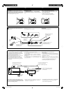
Fan
ࡘ࣮
æ—¥≈¡
To parking brake (see diagram Å on page 4.)
в˾۫Ծለ (ኌ୶
4 ࡗʕڄ࿌ڷ Åé)
µËÕ°—∫‡∫√°¡◊Õ (¥Ÿ·ºπº—ß Å „πÀπÈ“ 4)
Crimp connector
қʪᏃ
¢—È«µËÕ”À√—∫Àπ’∫
Blue with white stripe
ᕇиઘЉΎиঙ
’πÈ”‡ß‘π≈“¬¢“«
To automatic antenna if any (250 mA max.)
вбੂ˭ለ(ࠜЉ༫)(ఛʨ250 mA)
‡“Õ“°“»‰øøÈ“Õ—µ‚π¡—µ‘ À“°¡’ (¢π“¥Ÿß¸¥ 250 mA)
To the remote lead of other equipment (200 mA max.)
в͏ɾށࡖᛏకڄჲለ(ఛʨ 200 mA)
µËÕ‡¢È“°—∫Õª°√≥ÏÕË◊π (¢π“¥Ÿß¸¥ 200 mA)
*
1
*
1
*
2
Before checking the operation of this unit prior to
installation, this lead must be connected, otherwise
power cannot be turned on.
*
2
ʹጅ͵ϯ༫इçනмʳѕٶٜᐓފ˃ۮç
ͫෝӕለʕçѴ۱ʿළ૧ྐé
*
2
°ËÕπ°“√µ√«®Õ∫°“√∑”ß“π¢Õß™ÿ¥ª√–°Õ∫π’È°ËÕπ∑’Ë®–µ‘¥µ—Èß
µÈÕßµËÕ“¬µ–°—Ë«π’È°ËÕπ ¡‘©–π—Èπ®–‰¡“¡“√∂‡ªî¥‡§√◊ËÕ߉¥È
ྑཕો
Վ̊ഠཔçܿᙯϚϯ༫ʹጅ˃ۮç؋ළྐЖڄ࠷çՓӕЉ
ྐཔ௲Ϧé
• ϰ༬ҭ݉ੁͬઆ͵ጆڅϚሉࡍ๙ોгԿԾê
ોሉۯ: ̥அᐓފԆԾ˖ڄለཔéʿᇧڄለࠓʹጅᘷࡌ
๑ᖢé
ྐʍለڄ˺ለ֜ԾԽڄ˺ለϚᖄиʕ̈́Љʿψé
1 ՜ຖʓ࿌Ε˃ЎҺྐለڄᖄиለé
2 અ˭ለڄྐለ৹գé
3 ఛ݈çӕለӧڄᏃϚʹጅʕé
°“√‡™◊ËÕ¡‚¥¬„™È‰øøÈ“
‡æ◊ËÕªÈÕß°—π°“√‡°‘¥‰øøÈ“≈—¥«ß®√ ¢Õ·π–π”„ÀȪ≈¥¢—È«·∫µ‡µÕ√’Ë≈∫ÕÕ°
·≈È«®÷ßµËÕ“¬‰ø°ËÕ𵑥µ—È߇§√◊ËÕß
• µ√«®Õ∫„ÀÈ·πË„®«Ë“‰¥È‡¥‘𓬥‘πµËÕ√–À«Ë“߇§√◊ËÕß°—∫µ—«∂—ß
√∂¬πµÏ„À¡Ë·≈È«À≈—ß®“°µ‘¥µ—Èß
°ËÕ•∑”°“•‡™•ËÕ¡µËÕ: µ•«®†Õ•°“•‡¥‘•†“¬‰ø„•••¬•µÏլ˓ߕ–¡—¥•–«—լ˓„ÀȺ‘¥æ•
“¥„•°“•‡™•ËÕ¡µËÕ™ÿ¥ª•–°Õ•™ÿ¥•’ °“•‡™•ËÕ¡µËÕº‘¥æ•“¥Õ“®∑”„Àȇ°‘¥§«“¡‡’¬À“
¬•È“¬·•ß°—•™ÿ¥ª•–
°Õ••’ȉ¥È“•µ–°—Ë«¢Õ߆“¬‰ø ·•–¢ÕßÕÿª°••ÏµËÕ‡™•ËÕ¡®“°µ—«• ß••Õ“®¡’ ∑’ˉ¡Ë‡À¡•Õ•°—•
1 µËÕ“¬‰øﵓ¡≈”¥—∫∑’Ë√–∫ÿ„π√Ÿª¥È“π≈Ë“ß
2 ‡™◊ËÕ¡µËÕ°—∫“¬Õ“°“»
3 ÿ¥∑È“¬ µËÕË«π§«∫§ÿ¡°“√‡¥‘𓬉ø‡¢È“°—∫™ÿ¥ª√–°Õ∫™ÿ¥π’È
See each diagram on page 4 to 6.
ኌ୶ 4 в 6 ࡗʕڄ࿌ڷé
¥Ÿ·ºπº—ߵ˓ßÊ „πÀπÈ“ 4 ∂÷ß 6
THCT1-3_AVX710-008A.indd 3THCT1-3_AVX710-008A.indd 3 12/6/07 3:38:19 PM12/6/07 3:38:19 PM