


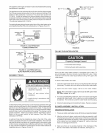

Chemicalvaporcorrosionoftheflue,blowerassemblyandventsystem
mayoccurifairforcombustioncontainscertainchemicalvapors.
Spraycanpropellants,cleaningsoJvents,refrigeratorandairconditioner
refrigerants,swimmingpoolchemicals,calciumandsodiumchloride,
waxes,bleachandprocesschemicalsaretypicalcompoundswhich
arepotentiallycorrosive.
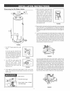
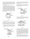
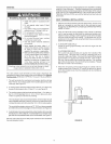
A.ALLAmRFROMINSBDEBUILDINGS:(SeeFigure10and11)
TheconfinedspaceshaJlbeprovidedwithtwopermanentopenings
communicatingdirectlywithanadditionalroom(s)ofsufficientvolume
sothatthecombinedvoJumeofallspacesmeetsthecriteriaforan
unconfinedspace.ThetotalinputofallgasutiJizationequipmentinstalled
inthecombinedspaceshallbeconsideredinmakingthisdetermination.
Eachopeningshallhaveaminimumfreeareaofonesquareinchper
1,000Btuperhour(22cm2/kW)ofthetotalinputratingofallgasutilization
equipmentintheconfinedspace,butnotlessthan100squareinches
(645cm2).Oneopeningshallcommencewithin!2 inches
(31cm)ofthetopandonecommencingwithin12inches(31cm)ofthe
bottomoftheenclosures.
OPE_'JING_i WATER
HEATER
kJ
VENT THROUGH
_ ROOF
J
OUTDOORS
FIGURE 11.
2.
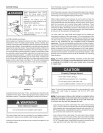
When communicating with the outdoors through vertical ducts, each
opening shall have a minimum free area of 1 square inch per 4,000
Btu per hour (5.5 cm2/kW) of total input rating of all equipment inthe
enclosure, see Figure 13.
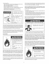
When communicating with the outdoors through horizontal ducts,
each opening shall have a minimum free area of 1 square inch per
2,000 Btu per hour (11 cm2/kW)) of total input rating of all equipment
in the enclosure, see Figure 14.
VENTILATION LOUVERS
(each end of attic)'_ VENT THROUGH
i
AIR OUTLET f_tt _ _VE_,JTTO
lllp 4T
INLETAIRDUDT_"_JII Jl WATER
(ends 1" above floor} _ HEATER
FIGURE 13.
4. When ducts are used, they shall be of the same cross-sectional
area as the free area of the openings to which they connect. The
minimum short side dimension of rectangular air ducts shall not be
less than 3 inches (7.6 cm), see Figure 14.
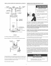
B. ALL AiR FROM OUTDOORS: (See Figures 12, 13 and 14)
The confined space shall be provided with two permanent openings,
one commencing within !2 inches (31 cm) of the top and one
commencing within !2 inches (3! cm) from the bottom of the enclosure.
The openings shall communicate directly, or by ducts, with the outdoors
or spaces (crawl or attic) that freely communicate with the outdoors.
1. When directly communicating with the outdoors, each opening shall
have a minimum free area of 1square inch per 4,000 Btu per hour
(5.5 cm2/kW) of total input rating of all equipment inthe enclosure,
see Figure 12.
VENTILATION LOUVERS
(each end of attic
VENT THROUGH
_. ROOF
VENTTO
OUTDOORS
VENTILATION LOUVERS
HGURE12.
6.
FIGURE 14.
Louvers and Grilles: in calculating free area, consideration shalJ be
given to the blocking effect of louvers, griJles or screens protecting
openings. Screens used shall not be smaller than 1/4 inch
(6.4 mm) mesh. ifthe free area through a design of louver or grille
is known, it should be used in calculating the size opening required
to provide the free area specified, ifthe design and free area is not
known, itmay be assumed that wood louvers will be 20_25 percent
free area and metal louvers and grilles will have 60-75 percent free
area. Louvers and grilles shall be fixed in the open position or
interlocked with the equipment so that they are opened automatically
during equipment operation.
Special Conditions Created by Mechanical Exhausting or Fireplaces:
operation of exhaust fans, ventilation systems, clothes dryers or
fireplaces may create conditions requiring special attention to avoid
unsatisfactory operation of installed gas utilization equipment.
11