


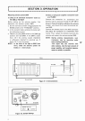
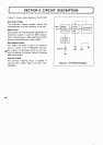

Measuring antenna system SWR
(i) Using an all solid-state transceiver (such as
a
TS-130s or TS-130V)
Before setting up the antenna coupler, first
determine the antenna system SWR.
a.
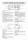
Set the controls
as
shown in Figure3-2. Set the
BAND switch to the "THROUGH" position.
b. In the transmit
mode, calibrate the meter with
the calibration control.
c.
Depress the CALISWR switch to the
SWR
(1)
position and read SWR. If the SWR
is
lower
than 1.5: 1 the antenna system impedance
is
sufficiently matched for practical use. If
above 1.5: 1, tune the system.
NOTE: In the event of too high an SWR (over
10:
I),
check the antenna system for
breaks or
a
short circuit.
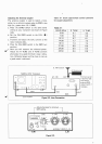
(ii)Using
a
tube power amplifier transceiver (such
as
a
TS-820)
Connect the transceiver (or transmitter) and
dummy load (or antenna) through the AT-1
30
as
shown in Figure 3-3. Before adjusting the antenna
coupler, you should first know the antenna sys-
tem SWR.
Connect the dummy load to the ANT connector
and adjust the transceiver (or transmitter) final
tuning. Then, replace the dummy load with the
antenna and measure the antenna-system SWR.
NOTE: During antenna measurements, your
transceiver may be operating under
heavy loading conditions.
el
Your signal may also interfere with
other stations. Use the least amount of
power possible, and complete measure-
ments as quickly as possible.
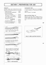
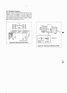
Ground lead
Figure 3-1. Interconnection
Coax.
T
I:
BAND
R
TUNE
CAL
PULL
LAMP
@
ANTENNA
k
1
1
Switch out set
CAL
(
control
Figure 3-2. Switch Settings
6
,
\