


21
ENGLISH |
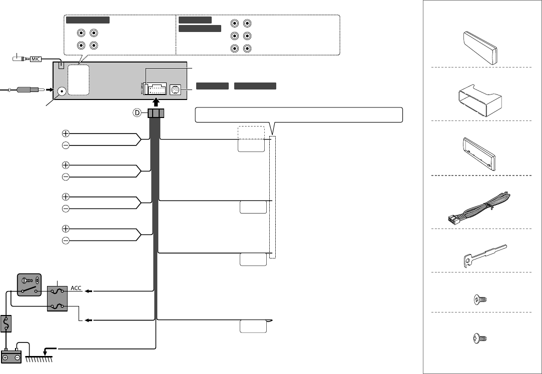
REMOTE CONT
STEERING WHEEL
REMOTE INPUT
ANT CONT
P. CONT
MUTE
FRONT
RL
REAR/SW
SW FRONT
RL
REAR
KDC
-
BT555U
KDC
-
X597KDC
-
BT355U
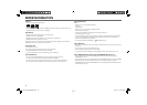
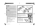
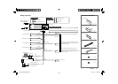
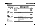
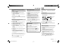
Wiring connection
Part list for installation
Fuse (10 A)
Rear/subwoofer output
Front output
Front output
Subwoofer output
Rear output
KDC
-
X597
/
KDC
-
BT555U
:
To the optional SiriusXM Connect Vehicle Tuner (commercially available) (
➜
8)
Antenna terminal
Car fuse box
Car fuse box
Battery
Ignition switch
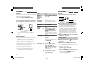
Blue/White
(Power control wire)
Red
(Ignition wire)
Yellow
(Battery wire)
Black (Ground wire)
To the metallic body or
chassis of the car
To the power control terminal when using the
optional power amplifier, or to the antenna control
terminal in the vehicle.
Brown
(Mute control wire)
Blue
White
Gray
Green
Purple
White/Black
Gray/Black
Green/Black
Purple/Black
To the terminal that is grounded when either
the telephone rings or during conversation. (To
connect the Kenwood navigation system, refer your
navigation manual.)
To front speaker (left)
To rear speaker (left)
To front speaker (right)
To rear speaker (right)
Light blue/yellow
(Steering remote control
wire)
To the steering wheel remote control adapter
(Not used)
If no connections are made, do not let the wire come out from the tab.
( ×4 )
( ×4 )
( ×2 )
( ×1 )
( ×1 )
( ×1 )
( ×1 )
A
Faceplate
B
Mounting sleeve
C
Trim plate
D
Wiring harness
E
Extraction key
F
Flat head screw
G
Round head screw
MIC (Microphone input
terminal) (
➜
10)
EN_KDC-X597[KWK0]f.indd 21EN_KDC-X597[KWK0]f.indd 21 10/18/12 10:31:04 AM10/18/12 10:31:04 AM