


1
UNPACKING AND CHECKING EQUIPMENT
Note: The following unpacking instructions are for use by your
KENWOOD dealer, an authorized KENWOOD service facility, or
the factory.
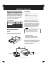
Carefully unpack the transceiver. We recommend
that you identify the items listed in the following table
before discarding the packing material. If any items
are missing or have been damaged during shipment,
file a claim with the carrier immediately.
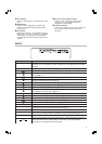
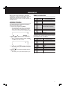
SUPPLIED ACCESSORIES
PREPARATION / INSTALLATION
metI rebmuNtraP ytitnauQ
)sesufhtiw(elbacrewopCDXX-9843-03E1
esuF
A52XX-4400-25F1
A4XX-8300-25F1
sdaptooFXX-2031-20J2
launamnoitcurtsnIXX-6681-26B1
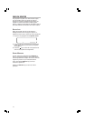
ANTENNA CONNECTION
For best performance:
• Use a properly adjusted, good-quality 50 Ω
antenna.
• Use a good-quality 50 Ω coaxial cable and
connector.
• Match the impedance of the coaxial cable and
antenna so that the SWR is 1.5:1 or less.
• Ensure that all connections are clean and tight.
The transceiver’s protection circuit will activate if the
SWR is greater than 2.5:1, but do not rely on
protection to compensate for a poorly functioning
antenna system. High SWR will cause the transmit
output to drop, and may lead to radio frequency
interference with consumer products such as stereo
receivers and televisions. You may even interfere
with your own transceiver. Reports that your signal is
garbled or distorted, especially at peak modulation,
may indicate that your antenna system is not
transmitting efficiently.
◆ Transmitting without first connecting an antenna or other
matched load may damage the transceiver. Always connect
the antenna to the transceiver before transmitting.
◆ Use a lightning arrestor to prevent fire, electric shock, or
damage to the transceiver.
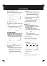
GROUND CONNECTION
•A good DC ground is required to prevent such
dangers as electric shock.
•A good RF ground is required for superior
communcations, against which the antenna
system can operate.
Both of these conditions can be met by providing a
good earth ground for your station. Bury one or more
ground rods or a large copper plate under the ground,
and connect this to the transceiver GND terminal.
Use heavy gauge wire or a copper strap, cut as short
as possible, for the connection. Ensure that all
connections are clean and tight.
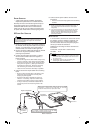
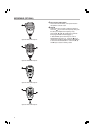
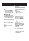
BASE STATION INSTALLATION
FOOT PADS
A set of foot pads are provided so that you can
protect the surface of your desk/table/shelf from
scratching. Apply the foot pads to the base of the
transceiver.
Earth ground
Black (—)
Red (+)
Fuse (25 A)
DC 13.6 V
DC Power supply
(20.5 A or more)
To antenna
Base Station Installation