


2
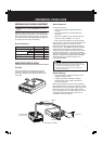
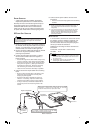
DC POWER SUPPLY CONNECTION
In order to use this transceiver as a base station, you
will need a separate 13.6 V DC power supply with a
current capacity of 20.5 A or higher (purchased
separately).
◆ Do not directly connect the transceiver to an AC outlet.
◆ Do not substitute the supplied DC power cable with a cable
with smaller gauge wires.
◆ Before connecting the DC power supply to the transceiver, be
sure to switch the DC power supply OFF.
◆ Do not plug the DC power supply into an AC outlet until you
make all connections.
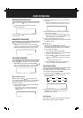
1 Connect the supplied DC power cable to the
regulated DC power supply and check that the
polarities are correct (Red: positive, Black:
negative).
2 Connect the connectorized end of the DC power
cable to the DC 13.6 V powerconnector on the
rear of the transceiver.
• Press the DC power cable connector firmly into the
connector on the radiotelephone until the locking tab
clicks.
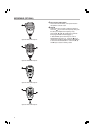
■ REPLACING FUSES
If the fuse blows, determine the cause then correct
the problem. After the problem is resolved, only
then replace the fuse. If newly installed fuses
continue to blow, disconnect the power plug and
contact your dealer for assistance.
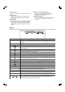
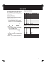
Following are the ratings for fuses used with this
transceiver:
Transceiver: 4 A (for KAT-1 antenna tuner)
DC cable: 25 A
◆ When replacing any fuse, be sure to replace it with a fuse
of the same value. Never replace a fuse with a fuse that
has a higher value.
◆ Replace blown fuses only after investigating and
correcting the cause of the failed fuse.
MOBILE INSTALLATION
Various electronic equipment in your vehicle may malfunction if
they are not properly protected from the radio frequency energy
which is present while transmitting. Electronic fuel injection,
anti-skid braking, and cruise control systems are typical examples
of equipment that may malfunction. If your vehicle contains such
equipment, consult the dealer for the make of vehicle and enlist
his/her aid in determining if they will perform normally while
transmitting.
Note: The following preparation instructions are for use by your
KENWOOD dealer, an authorized KENWOOD service facility, or
the factory.
INSTALLING THE TRANSCEIVER
For passenger safety, install the transceiver securely using an
optional mounting bracket so the transceiver will not break loose
in the event of a collision.
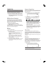
1 Mark the position of the holes in the dash by using
the mounting bracket as a template. Drill the
holes, then attach the mounting bracket using
self-tapping screws supplied with the bracket.
• Be sure to mount the transceiver in a location where
the controls are within easy reach of the user and
where there is sufficient space at the rear of the
transceiver for cable connections.
2 Connect the antenna and the supplied power
cable to the transceiver {page 3}.
3 Slide the transceiver into the mounting bracket
and secure it.
4 Mount the microphone hanger in a location where
it will be within easy reach of the user.
• The microphone and microphone cable should be
mounted in a place where they will not interfere with
the safe operation of the vehicle.
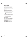
ANTENNA CONNECTION
For best performance:
• Use a properly adjusted, good-quality 50 Ω
antenna.
• Use a good-quality 50 Ω coaxial cable and
connector.
Coupling the antenna to the transceiver via feed lines
having an impedance other than 50 Ω reduces the
efficiency of the antenna system and can cause
interference to nearby broadcast television receivers,
radio receivers, and other electronic equipment.
Transmitting without first connecting an antenna or other matched
load may damage the transceiver. Always connect the antenna to
the transceiver before transmitting.