


20
On-Screen Menu (continued)
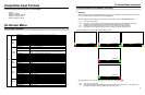
IMD CONFIGURATION SUBMENU (continued)
■
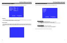
IMD ID #
The IMD ID # identifies each screen to the controlling device. When using the TSL protocol, the ID # of each screen
should be manually set in conjunction with the controlling device. When using the Image Video protocol, the ID # may
be set automatically by the controlling device, after each IMD is initially identified by IMD Name (see “IMD Name[S/N]”
below). Available ID #s are 000-255. When using the Marshall protocol, available ID #s are 001-254.
■
IMD Group #
Each screen can be assigned an IMD Group # when using the Marshall protocol. Available Group #s are 01-254.
■
IMD Name (S/N)
Use this setting to assign a name to each screen when using the Image Video or Marshall-IV protocols. The IMD name
is equivalent to the Image Video serial number and is used by the Image Video controlling device to identify
each screen. The default IMD Name(S/N) is “M00000.” It is recommended to maintain this naming scheme in order to
avoid serial number conflicts with other Image Video devices on the same serial bus. Each name can be up to 16
ASCII characters.
Press ENTER to edit the IMD Name. Use the and buttons to move the cursor. Press ENTER with the cursor on the
character to be changed and use the and buttons to scroll through character options. Press ENTER to choose a
character.
■
IMD Baud Rate
Use this setting to choose the baud rate. The baud rate must be set in conjunction with the controlling device. Available
baud rates are 300, 600, 1200, 2400, 4800, 9600, 19200, 38400, 57600, 115200. The TSL v4.0 protocol is fixed at
38400 bauds.
■
IMD Fixed Align
Use this setting to choose the horizontal alignment of the IMD text. IMD text can be justified on the left, center or right
of the screen. This setting is overridden when using IMD text via the Image Video protocol (alignment is set via Image
Video protocol).
■
IMD Fixed Color
Use this setting to choose the color of the IMD Fixed String text (see below). Available colors are red, green, and
yellow. This setting does not affect text color when using IMD text via the Image Video or TSL v4.0 protocols (text
color is set via the protocols).
■
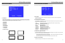
IMD Fixed String
Use this setting to display static IMD text on the screen. This setting is used to enter IMD text locally, when a serial
protocol is not used for remote control. The IMD Fixed String is saved after power cycle. The IMD Fixed String will be
overridden by serial protocol commands.
Press ENTER to edit the IMD Fixed String. Use the and buttons to move the cursor. Press ENTER with the cursor
on the character to be changed and use the and buttons to scroll through character options. Press ENTER to
choose a character.
5
Installation and Initial Setup
■
Unpacking
Carefully unpack the V-R201-IMD-TE monitor and verify that the following items are included:
• V-R201-IMD-TE Monitor
• V-PS12-6.6-A Power Supply with 2-Pin Twist Lock Connector
• Mounting Bracket
• Operating Instructions
Inspect the unit for any physical damage that may have occurred during shipping. Should there be any damage,
immediately contact Marshall Electronics at (800) 800-6608. If you are not located within the continental United States,
call +1 (310) 333-0606.
■
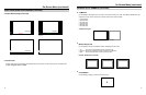
Installation
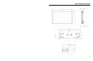
The V-R201-IMD-TE includes a mounting bracket which can be attached to any standard EIA 19” equipment rack,
occupying 7RU. When attached to a rack, the V-R201-IMD-TE extends about 1 5/8” beyond the surface of the
rack rails. The mounting bracket also allows the monitor to slide 6” forward, providing easy access to rear panel
connections. To extend forward the monitor, hold either side of the monitor in line with rails and pull forward evenly and
firmly. To lock the monitor against the rack, push on either side firmly until either side locks into place. NOTE: For
video wall applications, at least 1 inch should be left between monitors on either side, so that the monitor can
be extended. There are no handles on the front of the unit. Monitors can however be installed end to end in a
column.
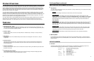
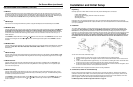
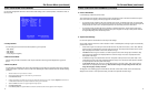
To rack mount the monitor, follow these steps:
1) Install the bracket in a rack using 4 screws, so the protruding hooks are pointing upwards.
2) Place the monitor against the rack adapter such the hooks on the bracket fit into the slots on the back of the
monitor.
3) Let the monitor slide downwards approximately 1 cm so the hooks are holding the monitor. Check both sides
to make sure they are level, ensuring that both hooks have properly secured the monitor.
4) On the back of the bracket, screw in and tighten the two thumbscrews. If either screw does not tighten, check
to make sure that the monitor is correctly attached to the bracket.
A VESA standard 75mm hole pattern also allows custom mounting installations.
■
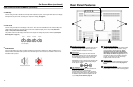
Connections, Power-On and Initial Setup
Plug the V-PS12-6.6A power supply into an AC power source (100-240 V @ 50/60 Hz). Attach the 2-pin twist lock
connector to the back of the monitor.
Connect the required cables for video signal input and output. (Power must be
applied to the V-R201-IMD-TE for the active loop-though output to be activated.) The monitor defaults to ‘ON’ when
power is supplied. Video will automatically be detected and displayed on the screen.
For IMD setup details, see IMD Configuration Submenu on page 19.
Hooks