


18
On-Screen Menu (continued)
OSD CONFIGURATION SUBMENU (continued)
■
LED Tally
Use this setting to enable or disable the LED Tally. When enabled, the yellow, red and green LEDs above each display
will respond to tally commands, according to the Tally Source setting (see page 21).
■
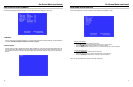
Time Code
Use this setting to enable time code display on the screen. Time code is de-embedded from the vertical ancillary data
(VANC) within the SDI signal. Two types of time code can be selected to display on the screen: LTC (linear time
code) or VITC (vertical interval time code).
The position of the time code display varies based on the aspect ratio setting and presence of IMD text (see Aspect
Ratio diagrams on page 14).
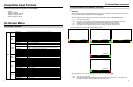
■
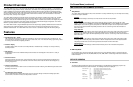
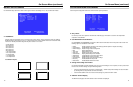
Audio Monitor
Use the Audio Monitor menu option to enable or disable the audio presence indicator icon. When enabled, this icon
indicates whether embedded audio is present in the SDI video input. A red circle and cross will flash on the icon if no
embedded audio is present.
Embedded Audio Present No Embedded Audio
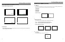
00:00:00:00
Time Code display
Hours Minutes Seconds Frames
7
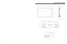
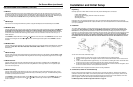
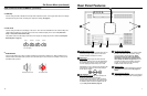
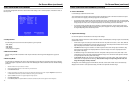
Rear Panel Features
HD-SDI Input and Output
The V-R201-IMD-TE has one HD-SDI input and one
active loop-through output. Note: No more than 4
screens should be connected in one loop.
Power Input
Connect the 12VDC input to the 2-Pin twist lock
power input connector. Power can be supplied from
the included power supply, or from a variety of DC
sources supplying at least 5.0 Amps at 12 Volts.
IMPORTANT: If using a power source other than the
included power supply, be sure that the polarity of
the DC input is correct:
Tally Interface (HD-15)
Both LED tally and OSD tally can be activated via
the HD-15 connector by connecting the
corresponding pin to ground. A variety of external
devices can be used to perform the contact closure.
No additional power should be supplied to the HD-
15 port. See pin-out details on page 22.
RS-422/485 Serial Interface
The RS-422/485 ports are used to remotely control
the IMD or all V-R201-IMD-TE features, using a
variety of industry standard protocols. (Note:
Connector/pin-out may need to be adapted
depending on protocol and controlling device
used. See pin-out details on page 22.) Only one
connection to either port is needed to control the
monitor. The second port can be used to loop
multiple monitors in the same bus.
Mounting Slots
These slots are used when attaching the monitor to
the included rack mount bracket. See page 5 for
details.
VESA 75mm Hole Pattern
A VESA-standard 75 mm hole pattern is provided to
accommodate a variety of custom mounting options.
1