


11
OPERA
TION
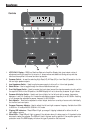
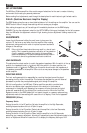
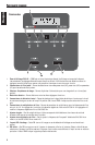
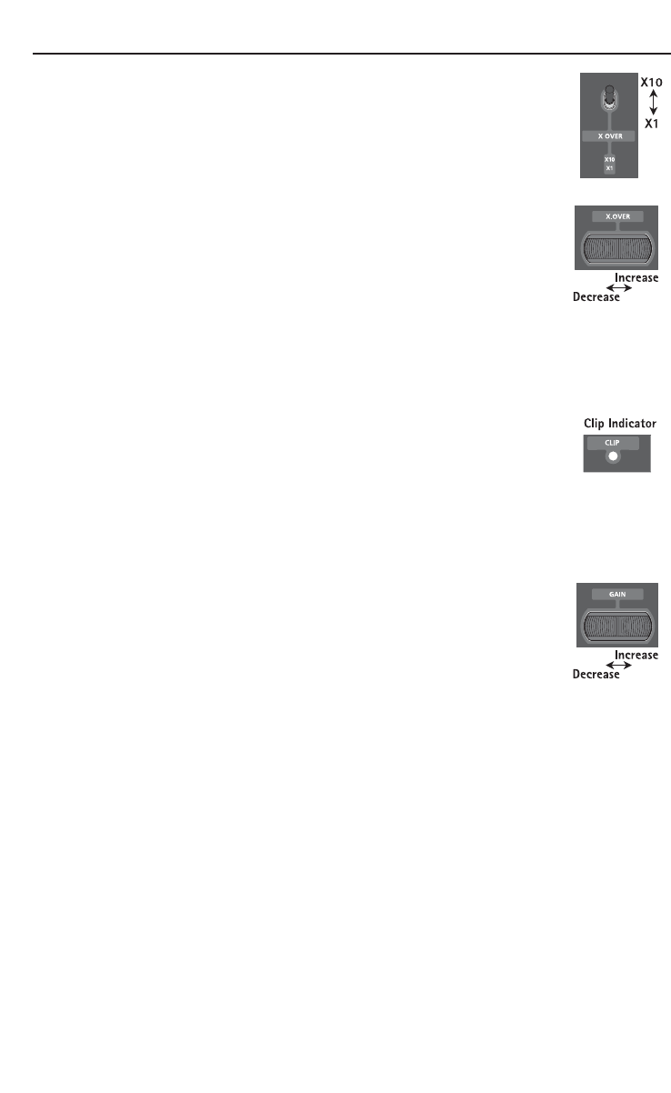
Multiplier Switch
This switch sets the multiplier for the crossover frequencies.
Placing the switch in the x10 position (Up) sets the adjustable crossover
frequency to 500-5000Hz.
Placing the switch in the x1 position (Down) sets the adjustable crossover
frequency to 50-500Hz.
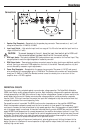
Frequency Adjustment Wheel
After setting the Frequency Switch and Multiplier Switch, use the Frequency Adjustment
Wheel to set the desired cut-off point.
Turning the adjustment wheel to the left decreases the set frequency.
Turning the adjustment wheel to the right increases the set frequency.
Quick Setting: Decrease the crossover frequency all the way down. With the system playing, increase the crossover
frequency up slowly until the desired crossover point is achieved.
GAIN
Clip Indicators
The MB Quart Q Series amplifiers offer a unique approach to setting the input sensitivity.
There is no need for digital multi-meters, oscilloscopes, distortion analyzers or any other
expensive pieces of equipment to set the input sensitivity of these amplifiers. The only
thing required is a test disc which contains 0 dB sine waves (45Hz and 1kHz). The on-
board clip detection circuitry eliminates the need for complex measurement devices. Since the MB Quart Q
Series amplifiers have a fully regulated power supply, the clip level of the amplifier is the same with or
without a load connected. This allows for system setup without damaging your speakers or your hearing.
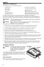
Gain Setup
NOTE: For maximum dynamic range and best signal to noise please read the following
procedure carefully, and if you do not understand the procedure, contact the
technical support department for assistance
Turning the adjustment wheel to the left decreases the set gain.
Turning the adjustment wheel to the right increases the set gain.
The loudest possible level on a CD recording is referred to as 0dB. Any level lower in output, is referred to as
–XdB.
The following procedure suggests using a CD with this (0dB) maximum level recorded on it, as well as
alternate lower output levels. When the setup is done as described below, using the maximum CD level will
result in lower average volume from the system, while using the lowest suggested level may result in
excessive distortion, and noise.
NOTE: Many users prefer some additional gain overlap in the system, to allow a higher “average” volume
level because of the amount of crest factor found in commercial recordings. In this case, begin with a
0dB signal level, and if you find the average volume not adequate and you are willing to sacrifice
some dynamic range and signal to noise performance for increased levels, try repeating the following
procedure, and substitute the 0dB test tones with –10dB or –15dB tones instead of the 0dB tracks.
We suggest using a specifically designed CD for this set-up, such as CD-104 from Autosound 2000.
The lower the level of the tone on the disc, the “louder” the average volume of the system will be, keeping in
mind that dynamic range and signal to noise performance is decreased as average volume is increased.