


4
DESIGN FEA
TURES
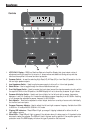
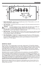
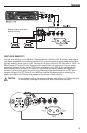
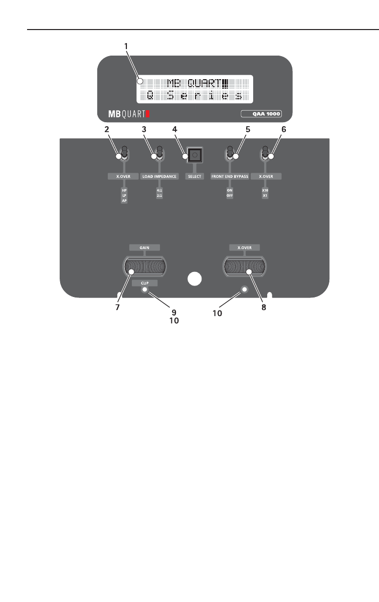
1. LCD R.E.A.D. Display – READ is a Realtime Electronic Amplifier Display that gives instant notice of
adjustments while the amplifier is turned on. It shows menus and selections during set-up and also
monitors the amplifier for thermal and short protection.
2. Crossover Switch – Is used for selecting High-Pass (HP), All Pass (AP), or Low-Pass (LP) operation for the
left and right speaker outputs.
3. Load Impedance Switch – Used to optimize power supply to drive a 2 or 4 ohm load (speaker).
4. Select Button – Use to toggle through the various features and set-ups.
5. Front End Bypass Switch – Used to reroute the input signal around the signal processing circuitry within
the amplifier. While in the ON position, the READ display will not to show any crossover or gain values.
6. Crossover Multiplier Switch – Used to set the multiplier for the left and right crossover frequencies
between x1 and x10. A setting of x1 leaves the adjustable crossover frequency from 50-500Hz. A setting
of x10 changes the adjustable crossover frequency to 500-5000Hz
7. Gain Adjuster – These can be adjusted to match output levels from a variety of source units individually
for the front and rear inputs.
8. Crossover Frequency Adjuster– Used to adjust the left and right crossover frequency. Variable from 50Hz
to 500Hz in x1 mode, and 500-5000Hz in x10 mode.
9. Clipping LED Indicators – These LEDs will light up orange if clipping is detected for either the left or
right speaker outputs.
10. Status LEDs – These LEDs will light up green if the adjuster above it is being used, or if the select button
was used to select the adjuster. The LEDs will flash in a green scrolling pattern if the amplifier goes into
protection mode. The READ display will show the type of protection that occurred.
Controls