


5
DESIGN FEA
TURES
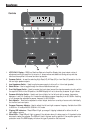
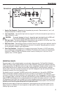
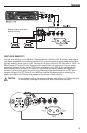
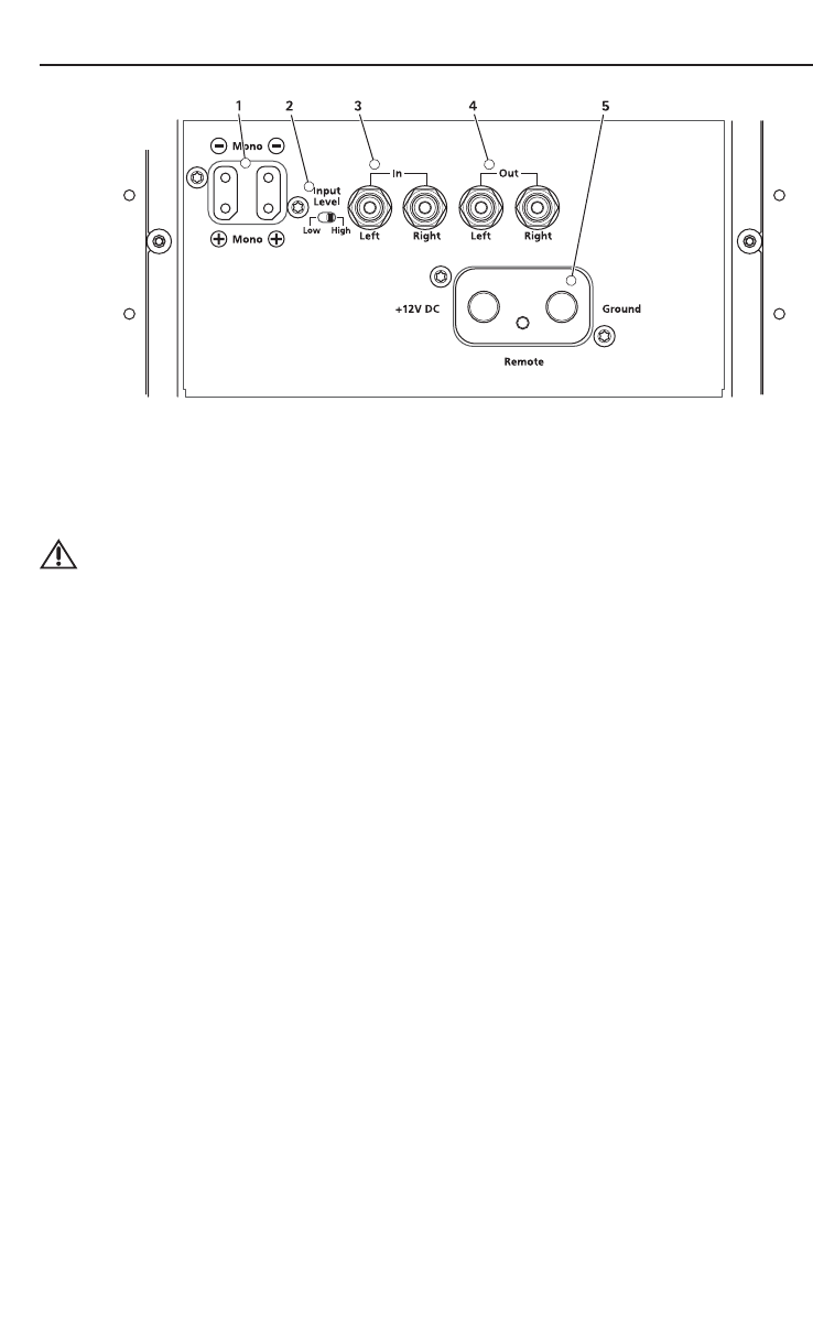
1. Speaker Plug Receptacle – Receptacle for the speaker plug connector. These connectors (+ and –) will
accept wire sizes from 12 AWG to 18 AWG.
2. Input Level Switch – High sets the input level to a range of 2 to 20 volts. Low sets the input level to a
range of 200mV to 2 volts.
CAUTION: To prevent damage to the unit, leave the input level switch set to HIGH until
the connected system has been identified for the correct setting.
3. RCA Input Jacks – The industry standard RCA jacks provide an easy connection for line level input. They
are gold-plated to resist the signal degradation caused by corrosion.
4. RCA Output Jacks – These outputs provide a convenient source for daisy-chaining an additional amplifier
without running an extra set of RCA cables from the front of the vehicle. These are pass-thru only and
are not effected by crossover or gain adjustments.
5. Power Plug Receptacle – Receptacle for the power plug connector. The power (+12V DC) and ground
wire connectors will accommodate up to a 2 AWG wire. The Remote wire connector will accommodate
sizes from 12 AWG to 18 AWG. The Remote terminal is used to remotely turn-on and turn-off the
amplifier when +12V DC is applied.
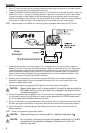
Connections
PROTECTION CIRCUITS
The power supply is fully protected against over and under voltage operation. The Pulse Width Modulator
(PWM) itself has an under voltage protection function. Both the battery voltage and the precision reference
voltage generated by the PWM are monitored. A sag of either voltage below a preset minimum results in the
power supply being turned off. Backup over and under voltage protection is also provided by a separate
monitor circuit. This circuit monitors the remote line input and is designed to stop the converter when that
voltage falls outside of the normal operating limits.
Two speed fan control is provided. The READ circuits monitor temperatures on the amplifier MOSFET bars.
When the temperature exceeds a preset level the fan is turned on at a low speed. If the temperature
continues to increase, the fans are switched to high speed operation. Also, the temperature of each MOSFET
set of the power supply is monitored. A thermistor mounted directly on each MOSFET bar monitors the power
supply MOSFET case temperature. At a preset temperature, the amplifier shuts down to allow it to cool. This
trip temperature is set higher than the amplifier fan control temperatures and will be the last resort thermal
protection. This should occur only under the most extreme conditions since these amplifier units utilize two
very quiet fans to move air across the heatsink fins for optimum control.
Because the power supply utilizes current mode control, pulse by pulse current limiting is inherent to the
design. So as not to interfere with normal operation at high amplifier output levels, this is set to occur at
relatively high current levels.