


7
Installation
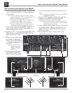
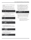
The MR85 can be placed upright on a table or shelf, stand-
ing on its four feet. It also can be custom installed in a
piece of furniture or cabinet of your choice. The four feet
may be removed from the bottom of the MR85 when it is
custom installed as outlined below. The four feet together
with the mounting screws should be retained for possible
future use if the MR85 is removed from the custom instal-
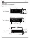
lation and used free standing. The required panel cutout,
ventilation cutout and unit dimensions are shown.
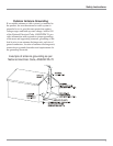
Always provide adequate ventilation for your MR85.
Cool operation
ensures the long-
est possible oper-
ating life for any
electronic instru-
ment. Do not in-
stall the MR85
directly above a
heat generating
component such
as a high powered
amplifier. If all the
components are
installed in a
single cabinet, a
quiet running ven-
tilation fan can be
a definite asset in
maintaining all the
system compo-
nents at the
coolest possible
operating tem-
perature.
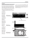
A custom cabi-
net installation
should provide the
following mini-
mum spacing di-
mensions for cool
operation. Allow
at least 2 inches
(5.08 cm) above
the top, 2 inches
(5.08cm) below
the bottom and
Installation
4 -
7/8
"
12.38cm
17-
1/16
"
43.34cm
Cutout Opening for Custom Mounting
MR85 Front Panel
Custom Cabinet Cutout
14"
35.56cm
14"
35.56cm
15-
1/16
"
38.26cm
17/32
"
1.35cm
Cutout Opening
for Ventilation
Cutout Opening for Ventilation
Support
Shelf
Cabinet
Front
Panel
Chassis
Spacers
MR85 Side View
in Custom Cabinet
MR85 Bottom View
in Custom Cabinet
1
"
2.54cm
1 inch (2.54 cm) on each side of the AM/FM Tuner, so that
airflow is not obstructed. Allow 20 inches (50.8 cm) depth
behind the front panel. Allow 1 inch (2.54 cm) in front of
the mounting panel for knob clearance. Be sure to cut out a
ventilation hole in the mounting shelf according to the di-
mensions in the drawing.