


SECTION TWO - Installation
961 INSTALLATION MANUAL Revision A Page 19
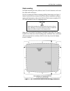
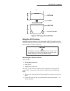
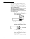
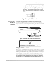
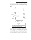
assembly forward until contact seats in insulator. Slide
outer ferrule over braid and up against connector
body. Crimp outer ferrule using Cavity A of tools spec-
ified above. The connector ferrule-to-cable junction
can be sealed and protected using adhesive-lined heat
shrink.
Figure 9: Completed BNC connector
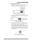
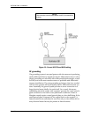
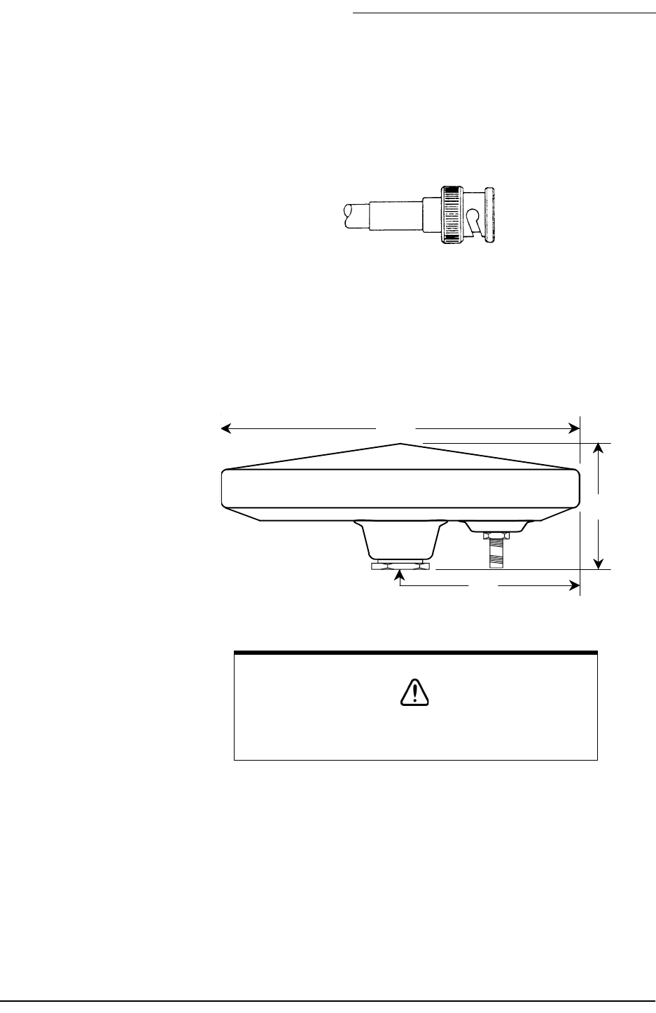
Installing the
AN205-P
antenna
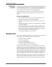
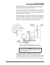
The combo antenna provides for an easier, more compact, and bet-
ter-looking installation, and in many cases, the loop antenna design
improves the noise rejection of signals interfering with differential signals.
Figure 10: Combo GPS/DGPS antenna (AN205-P)
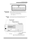
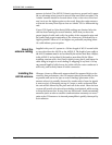
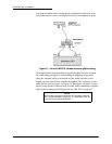
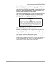
Wiring the AN205-P antenna
When you use the AN205-P combo antenna, a cable “splitter” is required
to separate the signal path of the single cable from the antenna into two
cables for connection to the 961. For the proper installation of the splitter,
refer to “Figure 11: Correct AN205-P (combo antenna) splitter wiring”
below. The splitter should be located near the unit for convenience, but
may be situated virtually anywhere along the length of the maximum
100 feet of RG-59 GPS cable, without appreciable signal loss. Note, how-
CAUTION!
The combo antenna must be used with a minimum of 20 feet
of cable, and no more than 100 feet. Any unused length must
be coiled up; do not cut it to less than 20 feet!
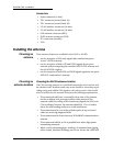
7.00
2.5
3.5
TNC