


961 INSTALLATION MANUAL Revision A Page 73
Numerics
8410 ACU
assembly diagram
23
cables
23
components
22
evaluating temporary locations before
mounting
22
mounting
22
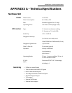
technical specifications
72
using the AN205-P antenna with
22
using with the AN150 antenna
22
wiring with AN150 antenna
24
961
activating
26
interfacing
45
servicing and maintaining
57
testing and troubleshooting
32
turning off
31
wiring
12
A
accuracy, viewing estimated
30
advisory message
28, 29
Alarm Out pins
46
AN150 antenna
17
cable lengths
16
choosing the location
14
flaring the end of the cable braid
18
mounting recommendations
7
stripping the coax cable jacket
18
tools needed for installation
17
using an 8410 ACU with
22
wiring
17
wiring with 8410 ACU
24
AN205-P antenna
cable lengths
16
choosing the location
15
dimensions
19
installing
19
mounting recommendations
8, 21
troubleshooting poor reception
16
wiring
19
antenna
8410.
See
8410 ACU
AN150.
See
AN150 antenna
AN205-P.
See
AN205-P antenna
cautions with L-band transmitting
16
choosing
14
COG and SOG readings and location
14
combination GPS/DGPS.
See
AN205-P an-
tenna
electromagnetic shading and
14
evaluating temporary locations before
mounting
22
grounding when disconnected
25
INMARSAT
14
separation distances between
15
troubleshooting installation
39
using a cable splitter
19
Antenna Coupling Unit.
See
8410 ACU
APB 0183 identifier
49
aux port
outputting DGPS corrections
55
pins
46
setting
53
setup parameters
54
turning input or output functions off
55
B
baud rate
47, 55
BCN UNHEALTHY message
37
beacon receiver
22
BEACON RX SELF-TEST AND SOFTWARE
message
36, 37
bench-testing the 961
8
BOD 0183 identifier
49
BWC 0183 identifier
49
C
cables
8410 ACU
23
AN150 length requirements
16
AN150 requirements
7
AN205-P length requirements
16
avoiding shortcuts
7
flaring the end of the braid (AN150)
18
flaring the end of the braid (AN205-P)
21
interface wiring
46
interface wiring screen
45
stripping the coax jacket (AN150)
18
stripping the coax jacket (AN205-P)
21
using a splitter
19
cautions
external fuse
13
fuse or circuit-breaker protection
13
checksums
47, 48, 53
clearance
yoke-mount
9, 10
COG
antenna location and
14
displaying
31
combo antenna.
See
AN205-P antenna
compatibility
5
components
9
configuring output formats
48
connections
illustration of 961 processor
13
verifying proper power cable
13
connectors
pin wiring
45
PL-259 (UHF)
23, 26
control head
flush-mount drilling dimensions
11
mounting
9
yoke mounting
9
yoke-mount dimensions
10