


11
Getting to Know the CD Receiver—Continued
The page numbers in parentheses show where you can find the main explanation for each item.
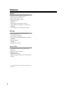
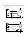
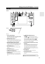
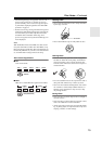
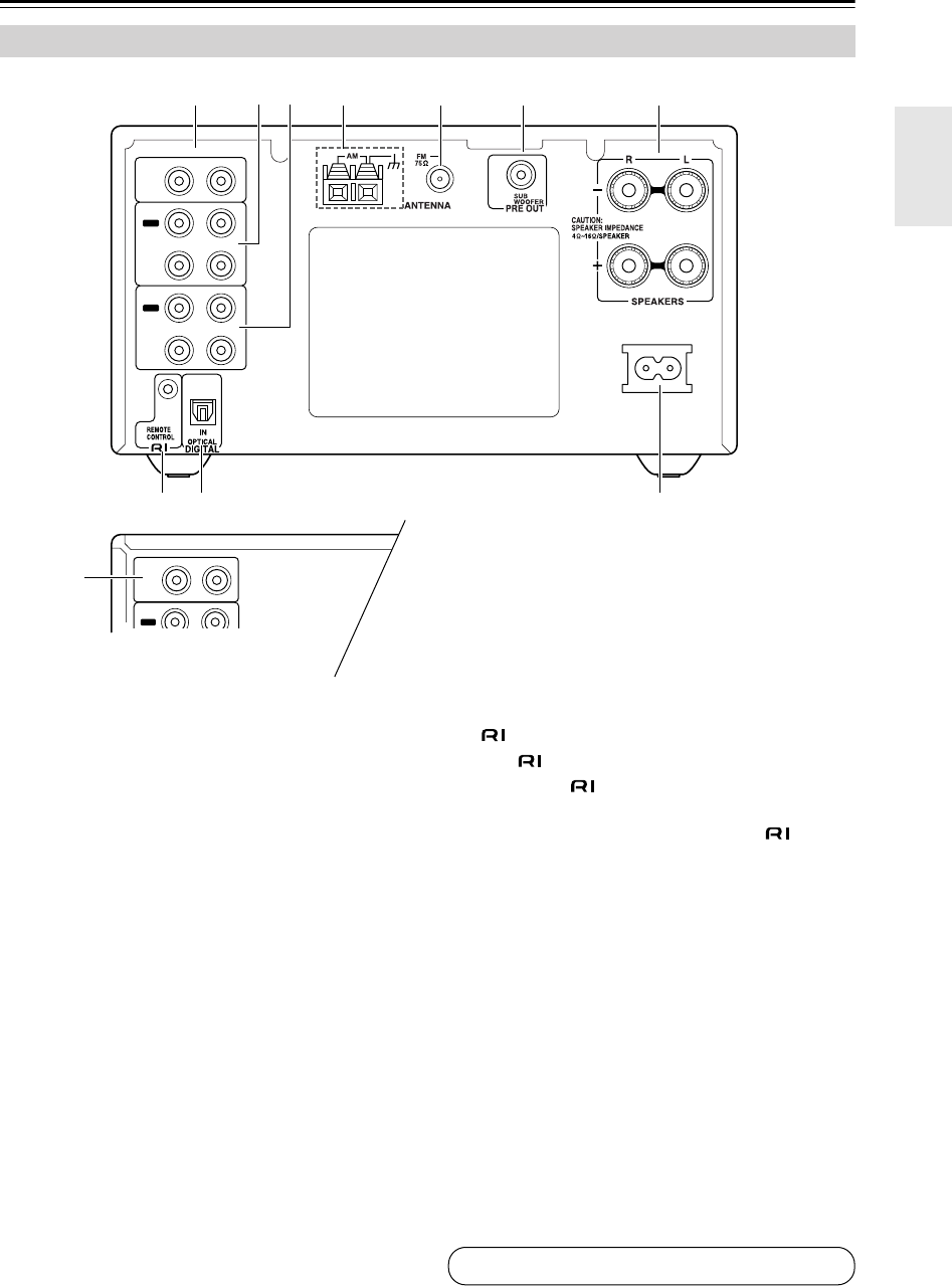
A LINE 1 IN (CR-515) (25)
This analog audio input is for connecting a compo-
nent with an analog output, such as a TV, or a turn-
table with a built-in phono equalizer.
B MD/TAPE IN/OUT (20, 21)
These analog audio inputs and outputs are for con-
necting a recorder with an analog input and output,
such as a MiniDisc recorder or cassette deck.
C DOCK/CDR IN/OUT (CR-515) (22, 23)
These analog audio inputs and outputs are for con-
necting a recorder with an analog input and output
such as a CD recorder, or an Onkyo RI Dock.
D AM ANTENNA (16, 17)
These push terminals are for connecting an AM
antenna.
E FM ANTENNA (16, 17)
This jack is for connecting an FM antenna.
F SUBWOOFER PRE OUT (19)
This jack is for connecting a powered subwoofer.
G SPEAKERS (18)
These terminal posts are for connecting speakers.
The North American CR-315 has push-type termi-
nals.
H REMOTE CONTROL (20–24)
This (Remote Interactive) jack can be con-
nected to an jack on another Onkyo component.
The CD receiver’s remote controller can then be
used to control that component. To use , you
must make an analog audio connection (RCA)
between the CD receiver and the other component,
even if they are connected digitally.
I OPTICAL DIGITAL IN (CR-515 Asian model
only) (24)
This optical digital audio input can be used to con-
nect a component with an optical digital output,
such as a CD recorder, MD recorder, games con-
sole, satellite tuner, or personal computer. Use a
commercially available optical digital audio cable to
make the connection.
J AC INLET (25)
The supplied power cord is connected here.
K DOCK IN (CR-315) (22)
This analog audio input is for connecting an Onkyo
RI Dock.
Rear Panel
IN
DOCK
IN
IN
R
LINE 1
MD/
TAPE
L
IN
OUT
OUT
DOCK/
CDR
AC INLET
IN
OUT
R
MD/
TAPE
L
1
K
23 74 5 6
8 9 J
CR-515
CR-315
See pages 16–25 for connection information.