24
REMOTE specifications (continued)
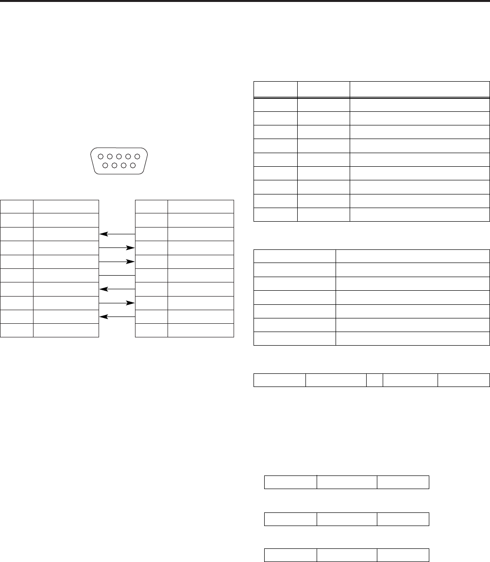
RS-232C connector
For the RS-232C connector pin layout and connections, refer
to the figure below and tables on the right.
<Note>
The RS-232C remote control specifications of this BT-
LH900A are not compatible with those of the conventional
BT-LH900.
If you wish to remotely control the BT-LH900A by using the
same remote control specifications as those of the BT-
LH900, then contact your dealer.
Pin No.
1
2
3
4
5
6
7
8
9
Signal
PC side BT-LH900A side
RS-232C
N.C.
RXD
TXD
DTR
GND
DSR
RTS
CTS
N.C.
Pin No.
1
2
3
4
5
6
7
8
9
Signal
N.C.
TXD
RXD
DSR
GND
DTR
CTS
RTS
N.C.
1
69
5432
87
RS-232C REMOTE operation
method
$ Connectors and signal names
Connector: D-SUB 9-pin (female)
Pin No. Signal name Explanation
1 N.C. Not connected
2 TXD Transmission data
3 RXD Reception data
4 DSR Connected inside.
6 DTR Connected inside.
7 CTS Connected inside.
8 RTS Connected inside.
5 GND Ground
9 N.C. Not connected
Signal level Conforms to RS-232C
Synchro system Tone pace synchro system
Transfer rate 9600 bps
Parity None
Data length 8 bit
Stop bit 1 bit
Flow control None
$ Communication Conditions
STX (02h)
OCommands are 3 characters following STX, finally
adding ETX.
OAdd a : (colon) after the command as required, and add
the data.
Command Data ETX (03h):
$ Command format
STX (02h) Command ETX (03h)
STX (02h) Data ETX (03h)
$ Response formats
1. Setting command response
2. Query command response
STX (02h) Error code
Error code
ER001 : Invalid command
ER002 : Parameter error
ETX (03h)
3. Error response


