


8
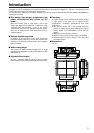
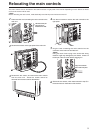
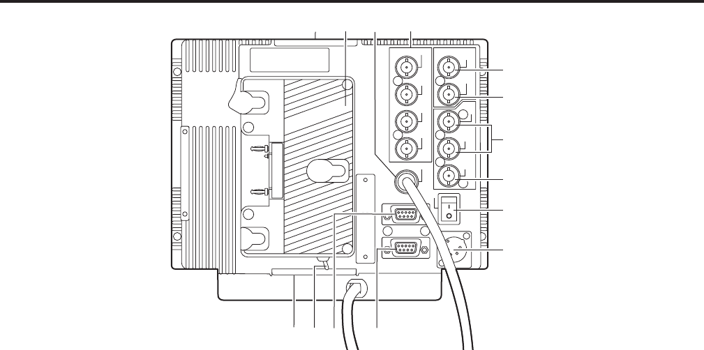
Parts and their functions (continued)
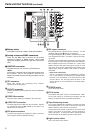
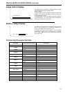
VIDEO OUT connector
The video signals are output from this connector. Signals
are passed through the : VIDEO IN connector and
output from this connector.
;
<
SDI input connectors
The SDI input signals are supplied to these connectors
which support automatic HD/SD switching.
=
SDI output connector
The SDI signals are output from this connector. It is the
switched output of the < SDI input connectors.
The signals displayed on the screen, whether they are the
ones supplied to the SDI 1 connector or SDI 2 connector,
are output.
However, the switched output signals are not output when
the component or video input signals have been selected.
When multiple monitors are connected in a
∗
daisy chain
pattern using the SDI active through-out, flicker or noise
may occur on the screen, depending on the quality of the
original signal, lengh of cables or the number of monitors
connected.
∗
Daisy chain connection:
This is a connection method for distributing a signal to
two or more devices by connecting the through-output
terminal of the first device to an input terminal of the
second device, the through-output terminal of the
second device to an input terminal of the third device,
and so on.
?
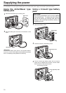
DC IN socket
The external DC power source is connected here. When
a DC power supply is connected concurrently with the
battery, the external power input takes precedence.
A
Light control switch
This is not used on this monitor.
@
Tripod fastening screws
Two screws (UNC3/8-16 compatible) for securing a tripod
are provided each on the top of the monitor and at its
bottom where the main controls are removed.
A removable screw spacer is provided in one of the screw
holes in the bottom of the monitor, and this supports a
UNC1/4-20 screw. To secure the tripod, use the hole that
fits the diameter of the fastening screw on the tripod.
>
POWER switch
This is the power switch.
8
GPI connector
When GPI signals are connected here, external
operations can be performed.
9
RS-232C connector
External operations can be performed under the RS-232C
standard.
:
VIDEO IN connector
The video input signals are supplied to this connector.
Y/G
VIDEO
IN
OUT
SDI 1
IN
SDI 2
IN
SWITCHED
OUT
PB/B
PR/R
SYNC
CONTROL
GPI
RS-232C
POWER
DC IN
6
7
8
9
:
;
<
=
>
?
5
@
@
A
6
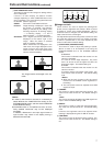
Analog component/RGBS connectors
These are the BNC input connectors for the analog
component (YP
BPR) or RGBS signals. When RGB
signals are supplied, external sync (gen-lock) can also be
used.
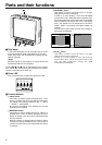
5
Battery holder
This holder is used with a battery made by Anton/Bauer.
7
CONTROL connector
The cable from the main controls is connected here.
<Note>
The monitor is shipped with the cable disconnected from
the connector. Prior to use, therefore, check out the
shape of the cable connector and plug it properly into this
connector.