


34
CQ-VX2200W
25
E
N
G
L
I
S
H
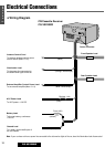
❏ Connect All Leads
Now that you have identified all the wires in the car,
you're ready to begin connecting them to the stereo
unit wires. The connection diagram (a Page 36 to
38) shows the proper connections and color coding
of the leads.
We strongly recommend that you test the unit
before making a final installation.
You can set the unit on the floor and make tempo-
rary connections to test the unit. Use electrical tape
to cover all exposed wires.
Important: Connect the red power lead last, after
you have made and insulated all other connections.
Ground
Connect the black ground lead of the power connec-
tor to the metal car chassis.
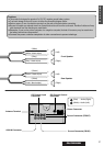
Speakers
Connect the speaker wires. See the wiring diagram
below for the proper hookups. Follow the diagram
carefully to avoid damaging the speakers and the
stereo unit.
The speaker used must be able to handle more than
41 W of audio power. If using an optional audio
power, the speakers should be able to handle the
maximum amplifier output power. Speakers with
low input ratings can be damaged.
Speaker impedance should measure 4 - 8
Ω, which
is typically marked on most speakers. Lower or
higher impedance speakers will affect output and
can cause both speaker and stereo unit damage.
CAUTION : Never ground the speaker cords. For
example, do not use a chassis ground system or a
three-wire speaker common system. Each speaker
must be connected separately using parallel insulat-
ed wires. If in doubt about how your car's speakers
are wired, please consult with your nearest profes-
sional installer.
Motor Antenna
Connect the car motor antenna lead to the blue
motor antenna relay control lead.
Battery
Connect the yellow battery lead to the correct radio
wire or to the battery fuse port on the fuse block.
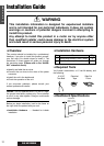
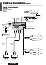
Installation Guide(continued)
Antenna
Connect the antenna by plugging the antenna lead
into the antenna receptacle.
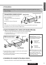
Equipment
Connect any optional equipment such as an amplifi-
er, according to the instructions furnished with the
equipment. Leave about 30 cm of distance between
the speaker cords/amplifier unit and the antenna/
antenna extension cord. Read the operating and
installation instructions of any equipment you will
connect to this unit.
Power
Connect the red power lead to the correct car radio
wire or to the appropriate fuse port on the fuse
block.
If the stereo unit functions properly with all these
connections made, disconnect the wires and pro-
ceed to the final installation.
Illumination
1.Connect to light switch, the control button are illu-
minated.
2.Can not find the light switch, connect the illumina-
tion lead (orange with white stripe) to accessory
(ACC).
❏ Final Installation
Lead Connections
Connect all wires, making sure that each connection
is insulated and secure. Bundle all loose wires and
fasten them with tape so they won't fall down later.
Congratulations! After making a few final checks,
you’re ready to enjoy your new auto stereo system.
Connect the power cord after completion of other
connections to prevent shortings.
❏ Final Checks
1. Make sure that all wires are properly connect-
ed and insulated.
2. Turn on the ignition to check the unit for prop-
er operation.
If you have difficulties, consult your nearest autho-
rized professional installer for assistance.