


17
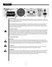
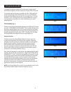
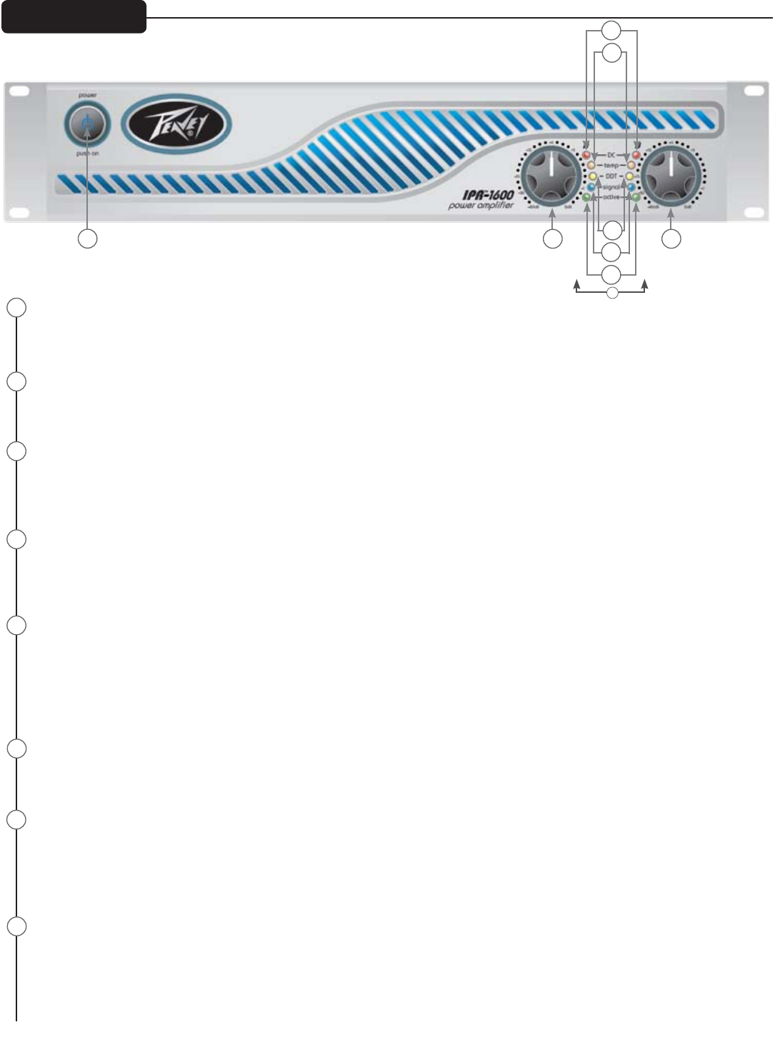
AC POWER SWITCH
This button triggers the relay that provides power to the amplifier. This unique power switch will glow blue (along with the
Peavey logo) in standby mode, indicating AC power has been connected to the amplifier but the amplifier has not yet been
turned on.
INDICATORS
The IPR
™
amplifiers feature five front-panel LED indicators per channel: ACTIVE, SIGNAL, DDT
™
, TEMP and DC. These LED
indicators inform the user of each channel’s operating status and warn of possible abnormal conditions.
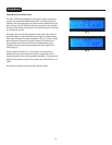
ACTIVE LED
The Active LED indicates that its channel’s output relay is closed and the channel is operational. It lights under normal
operation and remains on, even when the channel is in DDT gain reduction. These protection features leave the output
relay closed. If the Active LED goes off, there is no signal at the output connectors.
SIGNAL LED
This LED lights when its channel produces an output signal of about 4 volts RMS or more (0.1 volt or more at the input,
with 0 dB attenuation and standard x40 voltage gain). This signal indicates whether a signal is reaching and being
amplified by the amplifier.
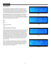
DDT
™
(DISTORTION DETECTION TECHNIQUE) LED
A channel’s DDT LED will light at the onset of clipping. If the LEDs are flashing quickly and intermittently, the channel is
just at the clip threshold. A steady, bright glow means the amp is clip limiting, or reducing gain to prevent severely clipped
waveforms from reaching the loudspeakers. See the Distortion Detection Technique section for more information. During
initial power-up the DDT LED will light to indicate that the RAMPUP
™
gain reduction circuitry is activated. This prevents
sudden signal bursts when the speaker relays are closed.
TEMP LED
In the unlikely event of an unstable thermal condition, amplifier protection will be activated and will shut down the
offending channel. The Temp LED will remain illuminated until safe operating temperatures have returned.
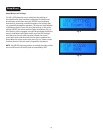
DC LED
In the event of abnormal operating conditions, the IPR has built-in amplifier protection. Under conditions that would
normally damage the power amplifier, the DC LED will illuminate and the channel will automatically attempt to restart to
correct the condition. If the amplifier does not return to normal operating status, contact your local authorized service
center.
INPUT ATTENUATORS
Whenever possible, set the attenuators fully clockwise to maintain optimum system headroom. The input attenuator
controls, located at the front panel (one for channel A, one for channel B), adjust gain for their respective amplifier
channels in all modes. See the specifications at the end of this manual for standard voltage gain and input sensitivity
information.
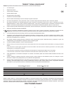
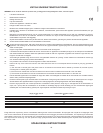
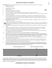
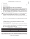
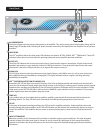
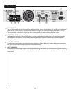
Front Panel
1
2
3
4
5
6
7
8
1
8 8
7
3
4
5
6
2
17