


4 C553M-C (3/03)
INSTALLATION
CABLE AND WIRING PREPARATION METHODS
There are four methods of installing the LWM41 wall mount. Cables can be fed directly into the rear of the LWM41 or through
the bottom of the mount arm. Conduit plates are supplied for added flexibility of installation. A rear entry, knock-off plate is
supplied with the mount arm and a bottom entry, gland/conduit plate is supplied with the LRD41A11 Series receiver.
Refer to one of the following sections to prepare wiring and cabling for your installation:
Rear Entry Without Conduit
Rear Entry With Conduit
Bottom Entry Without Conduit
Bottom Entry With Conduit
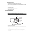
REAR ENTRY WITHOUT CONDUIT
1. Pull the cabling into and through the rear entry of the LWM41 wall mount. Feed the power cable through the right side of
the mount and the video/auxiliary/alarm cables through the left side of the mount. Leave enough slack for connections,
preferably four to six inches.
2. Install LWM41 wall mount (refer to the installation instructions supplied with the mount).
3. Proceed to
Installing the Switch Bracket
.
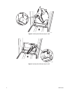
REAR ENTRY WITH CONDUIT
1. Secure the cable conduit to the block-off plate supplied with the LWM41 wall mount.
2. Pull the cabling into and through the rear of the mount. Feed the power cable through the right side of the mount and the
video/auxiliary/alarm cables through the left side of the mount. Leave enough slack to make all connections (preferably
four to six inches).
3. Install LWM41 wall mount (refer to the installation instructions supplied with the mount).
4. Proceed to
Installing the Switch Bracket
.
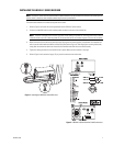
BOTTOM ENTRY WITHOUT CONDUIT
1. Install LWM41 wall mount (refer to the installation instructions supplied with the mount).
2. Remove the bottom plate of the mount arm and replace with the gland/conduit plate provided with the LRD41A11 Series
receiver.
3. Install the glands into the gland plate. Thread cabling/wiring through the glands. Do not install the BNC connector to the
video cable before threading the cable through the gland. The BNC connector will not fit through the PG-13 gland. Do not
use a gland sealing compound at this time.
4. Feed the power cable through the right side of the mount and the video/auxiliary/alarm cables through the left side.
Leave adequate slack for connections.
5. Tighten the glands and secure the gland/conduit plate to the bottom of the mount arm.
6. Install the BNC connector to the video cable.
7. Proceed to
Installing the Switch Bracket
.