


C553M-C (3/03) 5
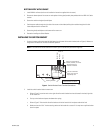
BOTTOM ENTRY WITH CONDUIT
1. Install LWM41 wall mount (refer to the installation instructions supplied with the mount).
2. Remove the bottom plate of the mount arm and replace with the gland/conduit plate provided with the LRD41A11 Series
receiver.
3. Secure the conduit to the gland/conduit plate.
4. Feed the power cable through the right side of the mount and the video/auxiliary/alarm cables through the left side.
Leave adequate slack for connections.
5. Secure the gland/conduit plate to the bottom of the mount arm.
6. Proceed to
Installing the Switch Bracket
.
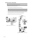
INSTALLING THE SWITCH BRACKET
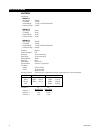
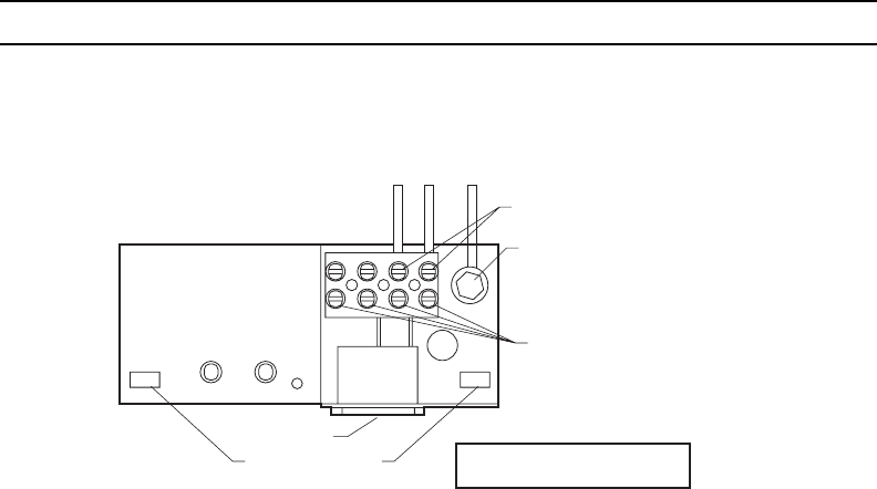
1. Connect the power cable to the terminal block located on the bottom of the switch bracket (refer to Figure 1). Make sure
the ground is connected for 120 VAC and 230 VAC operation.
NOTE: If the cable cannot be retracted from the mount, push it into the cavity behind the hinge base.
Power input terminals for
120VAC, 230VAC, or 24VAC
This set of terminals
factory set; not to be
adjusted by user.
Terminal ground for
120VAC or 230VAC
Power switch
Securing Notches
Neutral (Low)
Hot (High)
NOTE: Power connector cable
to receiver/driver not shown.
Ground
Power in
01280
Figure 1. Switch Bracket Power Terminal Connections
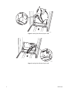
2. Install the switch bracket inside the mount arm:
a. Refer to Figure 2. Insert the notch on the right side of the switch bracket into the tab located in the back, right side
of the mount arm.
b. Push up on the bracket to depress the bottom bow spring.
c. Refer to Figure 3. Twist the left side of the bracket until the left notch clicks into place under the left tab.
d. Make sure the tabs “click” into the securing notches of the bracket for a secure fit. You may have to pull the bracket
down into place.