8 C553M-C (3/03)
CHANGING CAMERA VOLTAGE
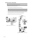
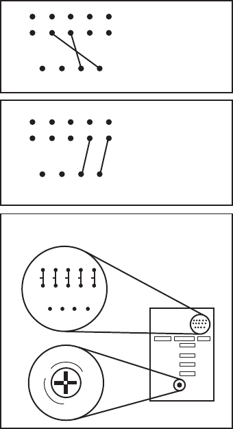
Set the camera voltage jumpers for the voltage that the camera will use. Refer to Figure 6 for the locations and settings for the
jumpers.
WARNING: CAMERA DAMAGE POSSIBLE. You will damage your camera if you connect it to the wrong connector on an
EH4700L or EH5700L Series enclosure. If your camera will use the same power as the enclosure, plug the camera into the
CAM1 socket on the circuit board inside the enclosure. If your camera will use 24 VAC and the enclosure will use either 120
VAC or 230 VAC, plug the camera into the CAM2 socket only.
If your camera will use 24 VAC, do NOT plug the camera into the CAM1 socket or you will damage your camera. CAM1 has
either 120 VAC or 230 VAC on it.
BE CAREFUL – REMEMBER – CAM1 IS ENCLOSURE POWER. NEVER PLUG YOUR CAMERA INTO CAM1 IF THE
CAMERA’S VOLTAGE IS DIFFERENT FROM THE ENCLOSURE’S VOLTAGE.
Camera Voltage Settings
24 VAC Camera
Voltage for
LRD41A11-1, -2, -3
120 V
24 V
AC-LOW
COM
AC-HI
PT-LOW
PT-HI
CAM-LOW
CAM-HI
120 V
24 V
AC-LOW
COM
AC-HI
PT-LOW
PT-HI
CAM-LOW
CAM-HI
120 VAC Camera
Voltage for
LRD41A11-1
and
230 VAC Camera
Voltage for
LRD41A11-3
120 V
AC-LOW
COM
AC-HI
PT-LOW
PT-HI
CAM-LOW
CAM-HI
Jumper/Strap Location on PC Board
Potentiometer Adjustment For Lens Voltage
NOTE: Camera Strapping
wires are blue.
24 V
Increase
Decrease
R65
01278
Figure 6. Camera Voltage Settings


