


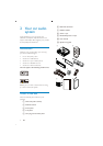

10
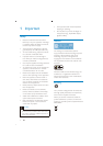
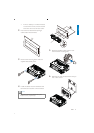
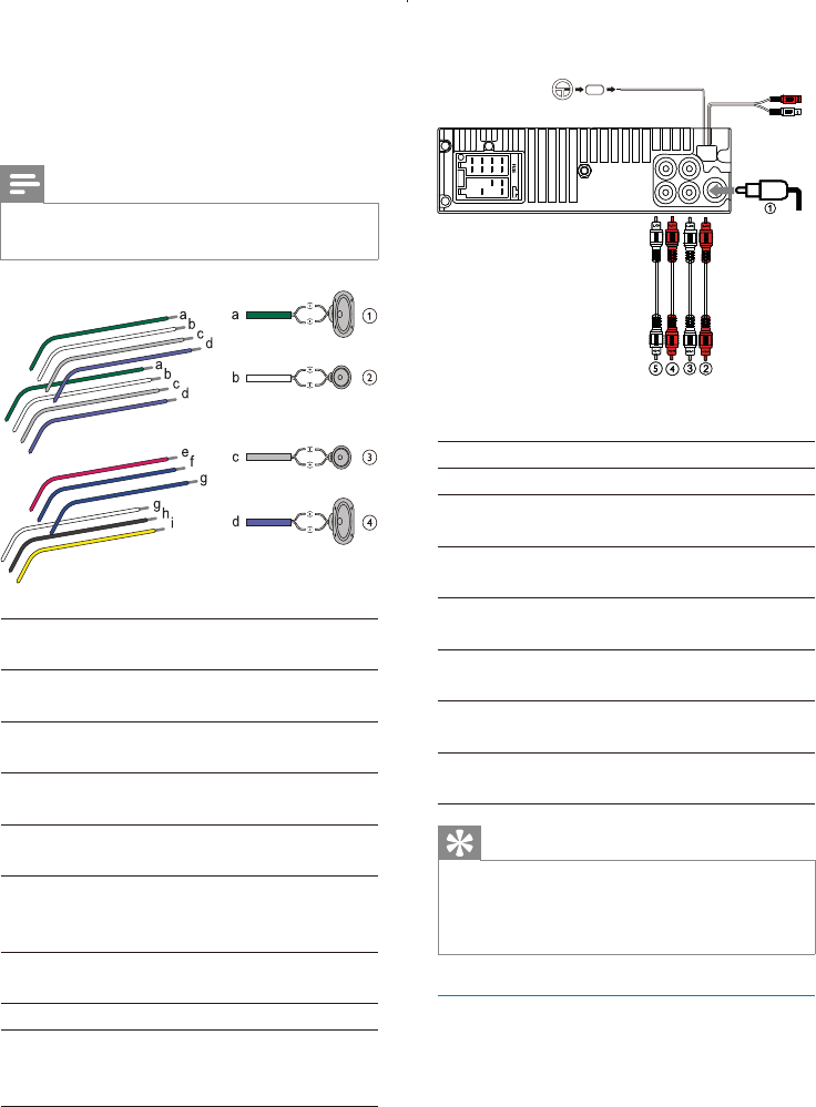
Connector Connect to
1 ANTENNA Antenna
2 FRONT LINE OUT
R (Socket)
Front right
speaker
3 FRONT LINE OUT L
(Socket)
Front left
speaker
4 REAR LINE OUT R
(Socket)
Rear right
speaker
5 REAR LINE OUT L
(Socket)
Rear left
speaker
6 OE REMOTE
(Purple)
OE Remote
7 REAR AUX (Yellow) Aux right/
left
Tip
The pin arrangement for the ISO connectors
depends on the type of vehicle you drive. Be
sure to make proper connections to prevent
damage to the unit.
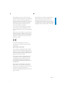
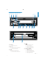
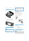
Mount into the dashboard
1 If the car does not have an on-board
the negative terminal of the car battery.
If you disconnect the car battery in
a car that has an on-board drive or
may lose its memory.
f
g
L
R
Rear
Front
L
R
Rear
Front
2 Check the car’s wiring carefully and
connect them to the supplied male
connector.
Note
Risk of danger! Please consult a professional to
perform the steps below!
1Green/black
strip
Left speaker (Rear)
2 White/black
strip
Left speaker (Front)
3 Gray/black
strip
Right speaker (Front)
4Purple/black
strip
Right speaker (Rear)
e Red Ignition key +12V DC
when ON/ACC
f Blue Motor/electric
antenna relay control
lead
g Blue/white
lead
hBlackGround
i Yellow To the +12V car
battery which is
energized at all times
3
EN