


2000 Feb 09 7
Philips Semiconductors Product specification
2 × 25 W high efficiency car radio power
amplifier
TDA1563Q
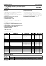
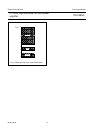
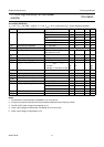
DC CHARACTERISTICS
V
P
= 14.4 V; T
amb
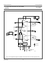
=25°C; measured in Fig.7; unless otherwise specified.
Notes
1. The circuit is DC biased at V
P
= 6 to 18 V and AC operating at V
P
=8to18V.
2. If the junction temperature exceeds 150 °C, the output power is limited to 5 W per channel.
SYMBOL PARAMETER CONDITIONS MIN. TYP. MAX. UNIT
Supplies
V
P
supply voltage note 1 6 14.4 18 V
I
q(tot)
total quiescent current R
L
= ∞−95 150 mA
I
stb
standby current − 150µA
V
C
average electrolytic capacitor voltage at pin 4 − 7.1 − V
∆V
O
DC output offset voltage on state −−100 mV
mute state −−100 mV
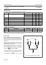
Mode select switch (see Fig.4)
V
ms
voltage at mode select pin (pin 6) standby condition 0 − 1V
mute condition 2 − 3V
operating condition 4 5 V
P
V
I
ms
switch current through pin 6 V
ms
=5V − 25 40 µA
Diagnostic
V
diag
output voltage at diagnostic outputs (pins 14 and
15): protection/temperature and detection
during any fault condition −−0.5 V
I
diag
current through pin 14 or 15 during any fault condition 2 −−mA
V
SC
input voltage at selectable clip pin (pin 12) clip detect at THD = 10% −−0.5 V
clip detect at THD = 2.5% 1.5 − 18 V
Protection
T
pre
prewarning temperature − 145 −°C
T
dis(BTL)
BTL disable temperature note 2 − 150 −°C