


TDA8566_6 © NXP B.V. 2007. All rights reserved.
Product data sheet Rev. 06 — 15 October 2007 2 of 21
NXP Semiconductors
TDA8566
2 × 40 W/2 Ω stereo BTL car radio power amplifier
3. Quick reference data
[1] The circuit is DC adjusted at V
P
= 6 V to 18 V and AC operating at V
P
= 8.5 V to 18 V.
[2] V
ripple
=V
ripple(max)
= 2 V (p-p); R
s
=0Ω.
[3] Common mode rejection ratio measured at the output (over R
L
) with both inputs tied together;
V
common
≤ 3.5 V (RMS); f
i
= 100 Hz to 10 kHz; R
s
=0Ω.
[4] Noise measured in a bandwidth of 20 Hz to 20 kHz.
4. Ordering information
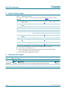
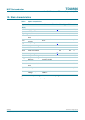
Table 1. Quick reference data
V
P
= 14.4 V; T
amb
=25
°
C; f
i
= 1 kHz; measured in test circuit of Figure 9; unless otherwise
specified.
Symbol Parameter Conditions Min Typ Max Unit
V
P
supply voltage
[1]
6 14.4 18 V
I
ORM
repetitive peak output
current
- - 7.5 A
I
q
quiescent current R
L
= ∞Ω - 115 180 mA
I
stb
standby current - 0.1 10 µA
Z
i
input impedance differential 100 120 150 kΩ
P
o
output power R
L
=4Ω; THD = 10 % 21 25 - W
R
L
=2Ω; THD = 10 % 33 40 - W
SVRR supply voltage ripple
rejection
operating
[2]
50 60 - dB
α
cs
channel separation P
o
= 25 W; R
s
=10kΩ 45 50 - dB
CMRR common mode rejection
ratio
R
s
=0Ω
[3]
60 75 - dB
G
v
closed loop voltage gain 25 26 27 dB
V
n(o)
noise output voltage operating; R
s
=0Ω
[4]
- 85 120 µV
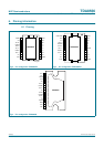
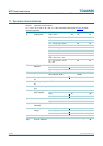
Table 2. Ordering information
Type number Package
Name Description Version
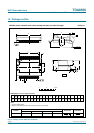
TDA8566TH HSOP20 plastic, heatsink small outline package; 20 leads; low stand-off height SOT418-3
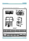
TDA8566TH1 HSOP24 plastic, heatsink small outline package; 24 leads; low stand-off height SOT566-3
TDA8566Q DBS17P plastic DIL-bent-SIL power package; 17 leads (lead length 12 mm) SOT243-1