


TDA8566_6 © NXP B.V. 2007. All rights reserved.
Product data sheet Rev. 06 — 15 October 2007 10 of 21
NXP Semiconductors
TDA8566
2 × 40 W/2 Ω stereo BTL car radio power amplifier
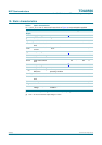
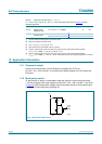
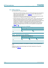
11. Dynamic characteristics
Table 8. Dynamic characteristics
V
P
= 14.4 V; T
amb
=25
°
C; R
L
=2
Ω
; f
i
= 1 kHz; measured in test circuit of Figure 9; unless
otherwise specified.
Symbol Parameter Conditions Min Typ Max Unit
P
o
output power THD = 0.5 % 25 30 - W
THD = 10 % 33 40 - W
THD = 30 % 45 55 - W
V
P
= 13.5 V; THD = 0.5 % - 25 - W
V
P
= 13.5 V; THD = 10 % - 35 - W
THD = 0.5 %; R
L
=4Ω 16 19 - W
THD = 10 %; R
L
=4Ω 21 25 - W
THD = 30 %; R
L
=4Ω 28 35 - W
V
P
= 13.5 V;
THD = 0.5 %; R
L
=4Ω
-14-W
V
P
= 13.5 V; THD = 10 %;
R
L
=4Ω
-22-W
THD total harmonic
distortion
P
o
= 1 W - 0.1 - %
V
CLIP
= 0.6 V
[1]
-8-%
P
o
= 1 W; R
L
=4Ω - 0.05 - %
B power bandwidth THD = 0.5 %; P
o
= −1dB
with respect to 25 W
-20to
20000
-Hz
f
ro(l)
low frequency roll
off
−1dB
[2]
-25-Hz
f
ro(h)
high frequency roll
off
−1 dB 20 - - kHz
G
v
closed loop voltage
gain
25 26 27 dB
SVRR supply voltage
ripple rejection
operating
[3]
50 60 - dB
mute
[3]
50--dB
standby
[3]
80--dB
Z
i
input impedance differential 100 120 150 kΩ
single-ended 50 60 75 kΩ
|∆Z
i
| input impedance
mismatch
-2-%
V
n(o)
noise output
voltage
operating; R
s
=0Ω
[4]
- 85 120 µV
operating; R
s
=10kΩ
[4]
- 100 - µV
mute; independent of R
s
[4]
-60-µV
α
cs
channel separation P
o
= 25 W; R
s
=10kΩ 45 50 - dB
|∆G
v
| channel unbalance - - 1 dB