


TDA8566_6 © NXP B.V. 2007. All rights reserved.
Product data sheet Rev. 06 — 15 October 2007 6 of 21
NXP Semiconductors
TDA8566
2 × 40 W/2 Ω stereo BTL car radio power amplifier
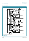
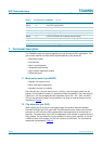
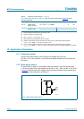
7. Functional description
The TDA8566 contains 2 identical amplifiers and can be used for BTL applications. The
gain of each amplifier is fixed at 26 dB. Special features of this device are:
• Mode select switch
• Clip detection
• Short-circuit diagnostic
• Temperature pre-warning
• Open-collector diagnostic outputs
• Differential inputs
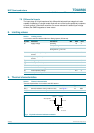
7.1 Mode select switch (pin MODE)
•
Standby: low supply current
• Mute: input signal suppressed
• Operating: normal on condition
Since this pin has a very low input current (< 40 µA), a low-cost supply switch can be
applied. To avoid switch-on plops, it is advisable to keep the amplifier in the mute mode for
a period of ≥ 150 ms (charging the input capacitors at pins IN1+, IN1−, IN2+ and IN2−).
This can be realized by using a microcontroller or by using an external timing circuit as
illustrated in Figure 8.
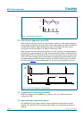
7.2 Clip detection (pin CLIP)
When clipping occurs at one or more output stages, the dynamic distortion detector
becomes active and pin CLIP goes LOW. This information can be used to drive a sound
processor or a DC volume control to attenuate the input signal and so limit the level of
distortion. The output level of pin CLIP is independent of the number of channels that are
being clipped. The clip detection circuit is disabled in a short-circuit condition, so if a fault
condition occurs at the outputs, pin CLIP will remain at a HIGH level. The clip detection
waveforms are illustrated in Figure 5.
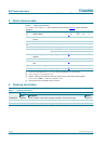
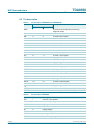
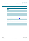
OUT2+ 10 channel 2 output positive
PGND2 11 power ground 2
OUT2− 12 channel 2 output negative
V
P2
13 supply voltage 2
MODE 14 mode select switch input (standby/mute/operating)
DIAG 15 short-circuit and temperature pre-warning diagnostic output
IN2+ 16 channel 2 input positive
IN2− 17 channel 2 input negative
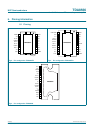
Table 4. Pin description TDA8566Q
…continued
Symbol Pin Description