


Connections
WARNING
! Use speakers over 50 W (output value) and
between 4 W to 8 W (impedance value). Do
not use 1 W to 3 W speakers for this unit.
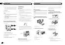
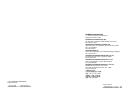
! The black cable is ground. When installing
this unit or power amp (sold separately),
make sure to connect the ground wire first.
Ensure that the ground wire is properly con-
nected to metal parts of the car’s body. The
ground wire of the power amp and the one of
this unit or any other device must be con-
nected to the car separately with different
screws. If the screw for the ground wire loos-
ens or falls out, it could result in fire, genera-
tion of smoke or malfunction.
Ground wire
Metal parts of car’s body
POWER AMP
Other devices
(Another electronic
device in the car)
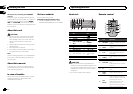
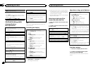
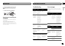
Important
! When installing this unit in a vehicle without
an ACC (accessory) position on the ignition
switch, failure to connect the red cable to the
terminal that detects operationof the ignition
key may result in battery drain.
O
N
S
T
A
R
T
O
F
F
ACC position NoACC position
! Use this unit with a 12-volt battery and nega-
tive grounding only. Failure to do so mayre-
sult in a fire or malfunction.
! To prevent a short-circuit, overheating or mal-
function, be sure to follow the directions
below.
— Disconnect thenegative terminal of thebat-
tery before installation.
— Secure thewiring with cable clampsor adhe-
sive tape. Wrap adhesive tapearound wiring
that comes intocontact with metal partsto
protect the wiring.
— Place allcables away from movingparts,
such as theshift lever and seatrails.
— Place allcables away from hotplaces, such
as near theheater outlet.
— Do notconnect the yellow cableto the battery
by passing itthrough the hole tothe engine
compartment.
— Cover anydisconnected cable connectors
with insulating tape.
— Do notshorten any cables.
— Never cutthe insulation of the powercable of
this unit inorder to share thepower with
other devices. Thecurrent capacity of the
cable is limited.
— Use afuse of the rating prescribed.
— Never wire thenegative speaker cable directly
to ground.
— Never bandtogether negative cables ofmulti-
ple speakers.
! When this unit is on, control signals aresent
through the blue/white cable. Connect this
cable to the system remote control of an ex-
ternal power amp or the vehicle’s auto-anten-
na relay control terminal (max. 300mA
12VDC). If the vehicle is equipped with a
glass antenna, connect it to the antenna
booster power supply terminal.
! Never connect the blue/white cable to the
power terminal of an external power amp.
Also, never connect it to the power terminal
of the auto antenna. Doing so may result in
battery drain or a malfunction.
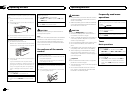
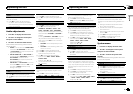
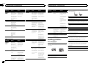
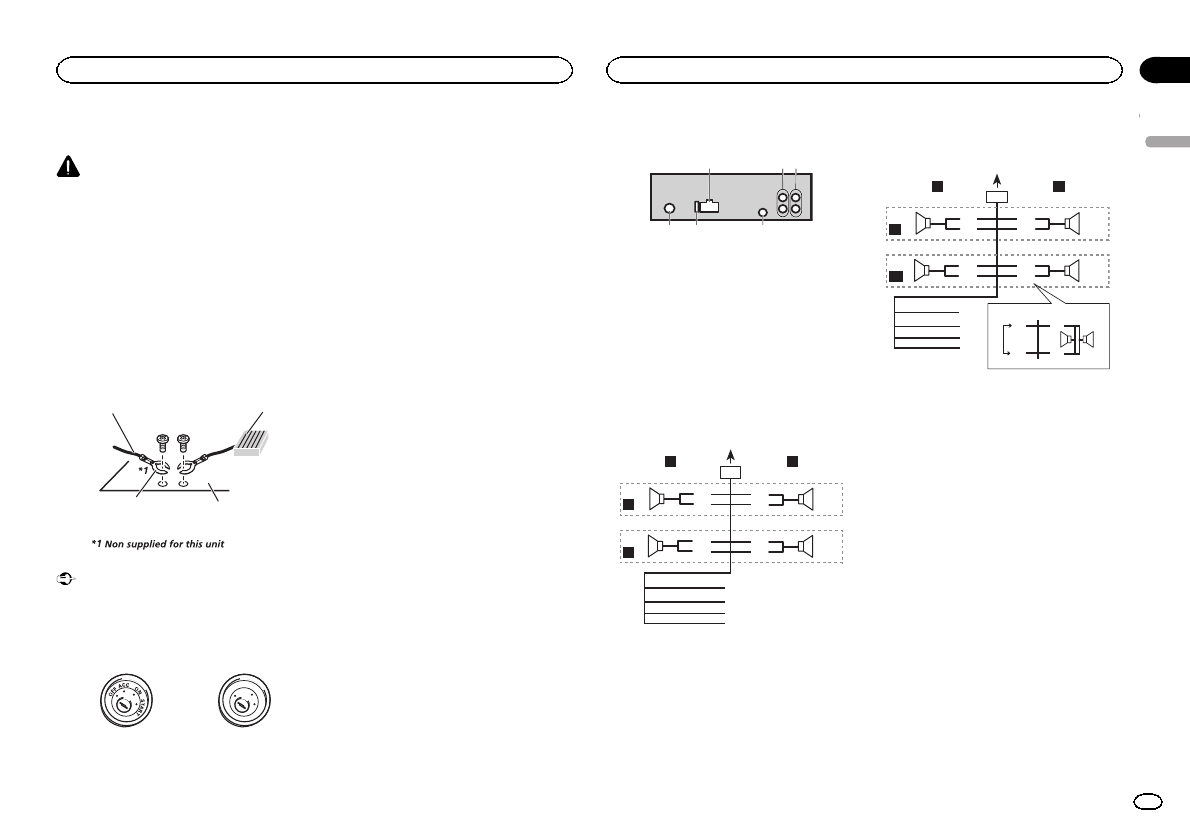
This unit
4 56
2
3
1
1 Power cord input
2 Rear output orsubwoofer output
3 Front output
4 Antenna input
5 Fuse (10 A)
6 Wired remoteinput
Hard-wired remote control adapter can be
connected (sold separately).
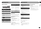
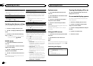
Power cord
Perform these connections when not connect-
ing a rear speaker lead to a subwoofer.
1
8
9
c
d
6
32
4
5
7
a
b
e
f
h
g
LR
F
R
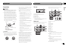
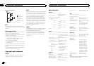
Perform these connections when using a sub-
woofer without the optional amplifier.
1
8
9
c
d
6
32
4
7
a
b
a
b
e
f
h
g
LR
F
SW
i
j
d
c
k l
1 To powercord input
2 Left
3 Right
4 Front speaker
5 Rear speaker
6 White
7 White/black
8 Gray
9 Gray/black
a Green
b Green/black
c Violet
d Violet/black
e Black (chassis ground)
Connect to a clean, paint-free metal location.
f Yellow
Connect to the constant 12 V supply termi-
nal.
g Red
Connect to terminal controlled by ignition
switch (12 V DC).
h Blue/white
Connect to system control terminal of the
power amp or auto-antenna relay control ter-
minal (max. 300 mA 12 V DC).
i Subwoofer (4W)
English
Installation
9
Section
Installation
En
03