


56
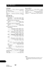
Connecting the Units
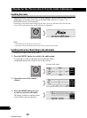
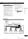
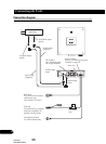
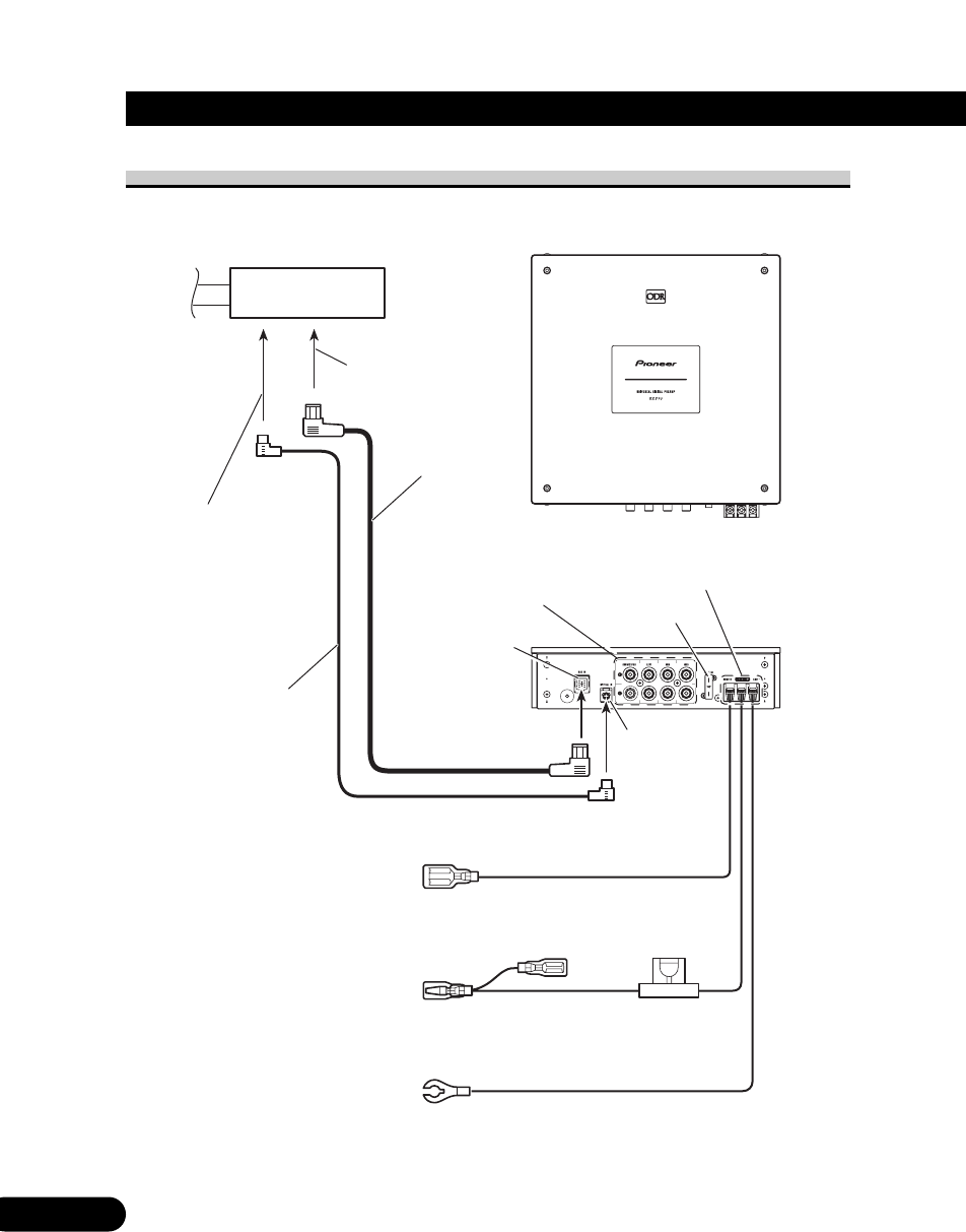
Connection diagram
Optical input
(blue)
IP-BUS input
(blue)
IP-BUS cable
(supplied)
optical cable
(supplied)
RS-D7R—
To IP-BUS output
(black)
To optical output
(black)
Fuse (4A)
Fuse holder
(4A)
Power terminal
Refer to “Connecting the power
terminal” on page 58.
Clear/red
To terminal always supplied
with power regardless of
ignition switch position.
Clear/black (ground)
To vehicle (metal) body.
Blue/white
To system control terminal
of the power amp
(max. 300 mA 12 V DC).
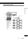
RCA output
See “Connecting the
RCA input amplifier.”
CRD3207
ENG/MASTER 96
56