


6 © 2011 Polk Audio—all rights reserved © 2011 Polk Audio—all rights reserved 7
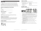
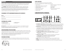
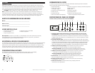
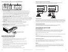
PA D2000.2 Power Inputs/Speaker Outputs
1. GND (Ground)—Connect this terminal directly to the metal chassis of the vehicle, using the shortest
wirenecessarytomakethisconnection.Alwaysusewireofthesamegaugeorlargerthanthe+12Vpower
wire. The chassis connection point should be scraped free of paint and dirt. Use only quality crimped and/or
soldered connectors at both ends of this wire. DO NOT connect this terminal directly to the vehicle battery
ground terminal or any other factory ground points.
2. REM (Remote Turn On)—Thisterminalturnsontheamplifierwhen+12Visappliedtoit.
Connect it to the remote turn on lead of the head unit.
3. +12V Power—Connect this terminal through a FUSE or CIRCUIT BREAKER to the positive terminal
of the vehicle battery or the positive terminal of an isolated audio system battery.
WARNING: Always protect this power wire by installing a fuse or circuit breaker of the appropriate
sizewithin12"ofthebatteryterminalconnection.
4. Fuse—These fuses (25A x 2) protect the amplifier against internal electrical damage and are meant
to protect only the amplifier. All other power connections should be fused at the power source.
5. Speaker Output—Connect the speakers here.
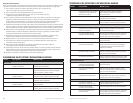
6. Terminal Adaptor—The adaptor enables the use of cable up to 0000AWG
forthegroundand+12Vconnections(seeillustrationbelow).
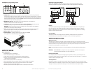
AMPLIFIER WIRING
Power Connections
• PAD2000.2FuseSize:2x25AMPATC.
• Powerconnectionsacceptupto4AWGwire.
• 4AWGpowerandgroundwirerecommendedforoptimalperformance.
• Connect+12Vtothebatterythroughfuseholder.Thisconnectionprovides
+12Vmainpowertotheamplifier.
• Powerwiremustbefusedwithin12"ofthebattery.
• Groundtheamplifierusingagoodchassisgroundascloseaspossibletotheamplifier.
• ConnectREMterminaltoremoteturn-onleadfromtheheadunit.Thisconnection
provides+12Vpowertoturn-ontheamplifier.
• Addextragroundwirebetweenthenegativeterminalofthebatteryandthechassis.
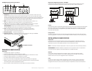
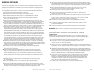
Speaker Wiring Diagram PA D2000.2
The Polk Audio PA D2000.2 amplifier offers two positive and two negative output terminals for ease of
connecting the speakers to the amplifier. The amplifier is stable to 2 Ohms per channel or 4 Ohms bridged.
Bridging
The amplifier is capable of bridging a left and right terminal into a single full range channel with higher output
power. For instance, the L-/R+ channels when wired as shown will increase the output power from 125W per
channel to a 500W channel (for a 4 Ohm load). The most common are shown in the figure above: two full range
channels or a bridged subwoofer channel.
Internal Bridging
Terminals that can be used in bridging mode are identified by the black boxes next to each terminal.
In the PA D2000.2, the two black boxes work together to create an internally bridged hookup.
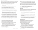
AMPLIFIER INSTALLATION
Mounting Locations
The location of your amplifier will depend on several important issues. Due to the low profile and compact
size of the Polk Audio PA D Series amplifier, there are many possible installation locations that will yield satisfactory
amplifier performance. Always mount the amplifier in a place that protects the amplifier from the elements.
In addition, mount the amplifier on a stable, flat surface.
NOTE: Mounting amplifiers upside down is not recommended and may cause premature thermal shutdown.
WARNING! DO NOT mOUNT any amplifier in the engine compartment. Amplifiers are not designed
to endure the harsh environment of an engine compartment.
Passenger Compartment
If you are going to mount the amplifier in the passenger compartment, make sure you have adequate room
forventilation.Whenmountingyouramplifierunderaseatorsimilararea,keepaminimumof1"ofclearance
around the amplifier for adequate cooling.
Trunk Compartment
Mounting your amplifier in the trunk provides excellent performance as long as you do not restrict the airflow
around the heatsink of the amplifier. For optimal results, mount the amplifier with as much clearance as possible.
This type of mounting will yield the best cooling due to the convection effect of the amplifier chassis.
L
R
L
INPUT OUTPUT
R
LPF
LPF
HPF LEVEL
BPF
FULL
HPF
X-OVER
HPF
X-OVER
FREQ x 10
FREQ x 1
FREQ x 10
FREQ x 1
20Hz400Hz 6V 200mV50Hz 500Hz
GND
12VREM
25A25A
L
LR
R
BRIDGED
L
R
L
R
LPFHPF LEVELLPFHPFLEVEL
HPF
BPF
FULL
HPF
BPF
FULL
ST
4CH
FRONT
REAR
X-OVER
X-OVER
FREQ x 10
FREQ x 1
FREQ x 10
FREQ x 1
50Hz 500Hz 50Hz 500Hz20Hz 400Hz 20Hz 400Hz6V 200mV 6V 200mV
CHANNEL
MODE
GND
12VREM
40A
35A
RL FL
RR
REAR
FRONT
FR
RR FR
RL FL
INPUT
SUB 1
SUB 2
SOURCE
SUB
INT
LEVEL
SUB
SONIC
LPF
REMOTE LEVEL CONTROL
INPUT
FR RR
FL RL
4CHST
CHANNEL
MODE
LPFHPF LEVEL
BPF
FULL
HPF
HPFFULL
HPF LEVEL
FRONT
REAR
6V 200mV
6V 200mV
20Hz 38Hz 40Hz 220Hz
40Hz 4000Hz 6V 200mV40Hz 400Hz80Hz4000Hz
SUB
GND
12VREM
40A40A
RL FL
SUB
RR FR
RR FR
SUB
RL FL
2876543
PA D1000.1
1432 5
27654b4a3a
PA D2000.2
3b
1432 5
21211
PA D4000.4
4a 5a 9a 10a
4b 5b 9b 10b6 7 8
14323
8
5
2
1
PA D5000.5
109 11 15 1612 13 14
1432
1
1
1
3 4 6 75 5
LL RR
BRIDGED
GND
12VREM
25A 25A
LL RR
BRIDGED
RL FL
RR
REAR
FRONT
FR
RR FR
RL FL
GND
12VREM
40A
GND
12VREM
40A
35A
RL FL
RR
REAR
FRONT
FR
RR FR
RL FL
GND
12VREM
40A
GND
12VREM
40A
35A
RL FL
RR
REAR
FRONT
FR
RR FR
RL FL
RL FL
SUB
RR FR
RR FR
SUB
RL FL
GND
12VREM
40A 40A
RL FL
SUB
RR FR
RR FR
SUB
RL FL
1Ω min 2Ω min
2Ω min
1000.1
4Ω min 2Ω min
2Ω min
2000.2
2Ω min
4000.4
2Ω min
2Ω min
2Ω min
2Ω min
2Ω min4Ω min/bridged
1Ω min 2Ω min
5000.5
1Ω min 4Ω min
2Ω min 2Ω min
2Ω min
4Ω min
4Ω min/bridged
4Ω min/bridged
6. Terminal Adaptor