12 © 2011 Polk Audio—all rights reserved © 2011 Polk Audio—all rights reserved 13
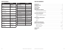
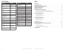
Amplifier PA D2000.2
Type Bridgeable
Class D MOSFET
Channels 2 channel
RMS Continuous Power
@ 4 Ohms
125 W x 2
RMS Continuous
Power @ 2 Ohms
250 W x 2
RMS Continuous Power
Bridged @ 4 Ohms
500 W x 1
Distortion at Rated Power < 0.1%
Minimum Impedance Bridged 4 Ohms
Minimum Impedance
NotBridged
2 Ohms
Signal-to-noise Ratio 105 dB
Frequency Response 20Hz - 20kHz
Damping Factor >100
Crossover Filter Slope
(dB/octave)
12 dB/octave
Filter Switch 3-position
(HPF, Full & BPF)
High Pass Filter
Frequency Range
20Hz - 4kHz
Amplifier PA D2000.2
Low Pass Filter
Frequency Range
50Hz - 5kHz
High Level Inputs (y/n/) No
Line Level Inputs (y/n) Yes
Line Level Outputs (y/n) Yes
LED Power Indicator Yes
LED Protection Indicator Yes
Input Sensitivity 200mV-6V
SupplyVoltage 10V-16V
Fusing & Power/Type (2) 25 Amp ATC
Power Connections 4 AWG
Ground Connections 4 AWG
Speaker Connections 12 AWG
Height 113/16"(46mm)
Depth 63/4"(171.5mm)
Width 81/4"(209.6mm)
Width w/ Terminal Adaptor 9"(228.6mm)
Weight 3.75 lbs (1.7 kg)
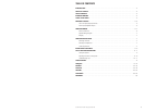
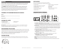
SPECIFICATIONS TABLE DES MATIÈRES
INTRODUCTION..............................................................................14
CONTENU DE LA BOÎTE.......................................................................14
ÉCOUTEZ BIEN ..............................................................................14
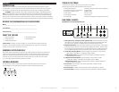
PONTAGE INTERNE .......................................................................... 14
OUTILS REQUIS.............................................................................. 15
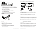
CONFIGURATION DES PANNEAUX..........................................................15 - 16
Entrées niveau de ligne/sorties/contrôles .....................................................15
Entrées de puissance/sorties haut-parleur.....................................................16
CÂBLAGE DE L’AMPLIFICATEUR ............................................................16 - 17
Connexion de l’alimentation ................................................................16
Diagramme du câblage des haut-parleurs .....................................................17
Pontage ................................................................................17
INSTALLATION DE L’AMPLIFICATEUR ..........................................................17
Emplacement ...........................................................................17
Habitacle ...............................................................................17
Coffre.................................................................................. 17
CONSEILS POUR L’INSTALLATION ..........................................................18 - 19
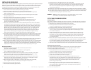
RÉGLAGE ET GUIDE DE DÉPANNAGE........................................................19 - 21
Vérificationdusystème....................................................................19
Réglagedusondusystème..............................................................19 - 20
Conseils de dépannage .................................................................20 - 21
SPÉCIFICATIONS............................................................................. 22
GARANTIE ..................................................................................63


