


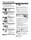

6
CD-DECK
SYNCHRO
CD-DECK
SYNCHRO
LINE OUT
OPTICAL
CONTROL
DIGITAL OUT
L
R
IN OUT
R L
C D
CONTROL
OUT
DIGITAL
OPTICAL IN
LINE OUT
OPTICAL
CONTROL
DIGITAL OUT
L
R
IN OUT
LR
LR
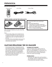
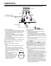
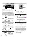
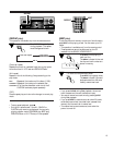
CONNECTIONS
Before making or changing the connections, switch off the power and disconnect the power cord from the AC outlet.
A Making connections
1 Connect the LINE OUT jacks of the changer to the input
jacks (CD or AUX) of the amplifier. Make sure the white
plugs are connected to the left (L) jacks and the red
plugs to the right (R) jacks.
• Do not connect the changer to the amplifier’s PHONO
jacks, as sound will be distorted and normal playback
will not be possible.
2 Connect the power cord to an AC wall outlet, making
sure the plug is inserted fully.
Note: If you connect the power cord to a “SWITCHED” AC
outlet on an amplifier, you will not be able to use the
changer’s memory function.
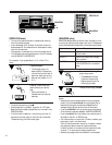
B Connecting the Optical Fiber Cable
Cautions:
• Insert the optical fiber cable plugs all the way into the
jacks.
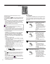
• Do not to fold or crimp the cable. When coiling an
optical fiber cable for storage, make sure the diameter of
the coil is 5-
7
/
8
inches (15 cm) or larger.
• Use an optical fiber cable with a length of 10 feet (3 m)
or less.
• Protect the optical fiber cable plugs
from scratches and dust.
• When the changer is not connected
using an optical fiber cable, be sure
to keep the protective dust cap
plugged into the optical digital
output jack at all times.
Connect the changer to an amplifier equipped with an
optical digital jack.
1. Remove the protective dust cap from the changer’s
OPTICAL DIGITAL OUT jack.
2. Use an optical fiber cable (not supplied, available at
your local RadioShack store) to connect the changer’s
OPTICAL DIGITAL OUT to the amplifier’s optical input
jack.
• Align the optical fiber cable plug with the optical digital
jack and fully insert the plug.
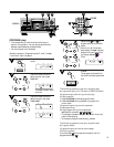
C System remote control with a stereo amplifier that
has the OSR mark
With a stereo amplifier bearing the OSR mark, connect the
CONTROL IN jack on the CD changer’s rear panel to the
amplifier’s CONTROL OUT jack. This lets you control the
CD changer’s Play, Stop, Pause, Track/Disc Search and Disc
Change functions using the amplifier’s remote control.
Notes:
• For instructions regarding connections and operation,
refer to the operating instructions provided with your
stereo amplifier.
• When a control cable is connected to the changer’s
CONTROL IN jack, direct control of the changer with the
remote control is not possible. Operate the changer with
the remote control by aiming it at the amplifier.
• Be sure to connect both of the control cable’s plugs
securely to the CONTROL IN and CONTROL OUT jacks.
• Be sure to turn off the power of the amplifier before
connecting the power cord and output cable.
• When only the digital output is connected, the remote
sensor of the amplifier does not function. To operate it,
connect the output cable to the stereo amplifier as well
as connecting the digital output.
C
Power Cord
A-2
Control Cable
C
Your CD Changer
Stereo Amplifier
WhiteRed
WhiteRed
Optical Fiber
Fable
A-1
B
Audio Cable
To the CONTROL IN Jack of the
Component Bearing the OSR Mark.
More than
5-
7
/
8
inches
(15 cm)