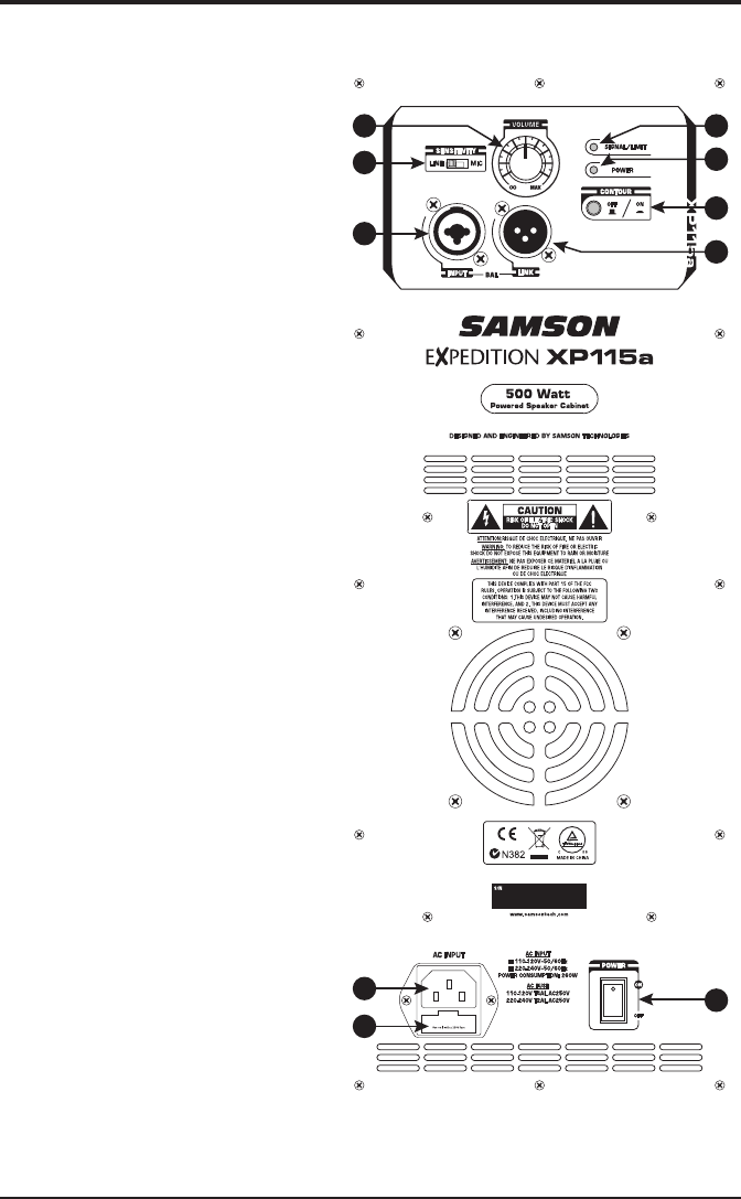
Rear Panel Layout
1
2
3
4 5
6
7
8
9
10
1. XLR & ¼” Combo Input - Use this
XLR / 1⁄4” input for balanced micro-
phone or line level device.
2. SENSITIVITY Switch (Mic/Line) -
The MIC position changes the gain
of the input jacks from MIC to LINE
level.
3. LINK Output - Male XLR connector
used to link multiple Expedition
cabinets.
4. VOLUME Control - This control
adjusts the overall signal level at
the input of the power amplifiers.
5. SIGNAL / LIMIT Indicator - This
indicator lights green when signal
is present. It will light red when
the amp is near the clipping point
and the limiter is engaged. If the
indicator frequently lights red,
turn down the VOLUME control on
the loudspeaker or turn down the
signal at the source, until the indi-
cator no longer lights red, or lights
occasionally with signal peaks.
6. POWER Indicator - This LED lights
GREEN when amp is active.
7. CONTOUR Switch - This switch
enables an equalization curve that
is ideal for music playback.
8. AC Power Inlet - Connect the
supplied standard IEC AC power
cable here.
9. Fuse Holder - The fuse holder
comes from the factory with the
appropriately rated fuse for your
model. If you need to change this
fuse for any reason, replace it with
one that has the same exact rating.
10. POWER Switch - Switches on the
Expedition’s main power.
7Expedition XP112/XP115


