


E
21
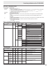
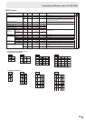
RS-232C command table
How to read the command table
Command: Command eld (See page 17.)
Direction: W When the “Parameter” is set in the parameter eld (see page 17), the command functions as described
under “Control/Response Contents”.
R The returned value indicated under “Reply” can be obtained by setting “????”, “
?” or “???+”
(repeater control) in the parameter eld (see page 17).
Parameter: Parameter eld (See page 17.)
Reply: Response (Returned value)
*1:
“●”
indicates a command which can be used in power standby mode regardless of the STANDBY MODE
setting.
“○” indicates a command which can also be used in power standby mode when STANDBY MODE is set to
STANDARD.
“–” indicates a command which cannot be used in power standby mode regardless of the STANDBY MODE setting.
*2: PN-ZB02 (optional) limitations
(A) When PN-ZB02 (optional) is not attached, (B) When PN-ZB02 (optional) is attached.
○ : The command can be used.
- : Error (ERR)
Power control/Input mode selection
Function
Command Direction
Parameter Reply Control/Response contents *1
*2
(A) (B)
POWER CONTROL POWR W 0
Switches to standby mode.
● ○ ○
1 Returns from standby mode.
R 0 Standby mode
1 Normal mode
2 Input signal waiting mode
INPUT MODE SELECTION INPS W 0 Toggle change for input mode. Terminals not selected in INPUT SELECT
cannot be selected.
●
○ ○
1 PC DVI-D
“ERR” when AV DVI-D is selected for DVI of INPUT SELECT.
-
○
2 PC D-SUB
○ ○
3 AV COMPONENT
“ERR” when PC RGB is selected for BNC of INPUT SELECT.
-
○
4 AV VIDEO -
○
6 PC RGB
“ERR” when AV COMPONENT is selected for BNC of INPUT SELECT.
-
○
7 AV DVI-D
“ERR” when PC DVI-D is selected for DVI of INPUT SELECT.
-
○
8 AV S-VIDEO -
○
9 AV HDMI
“ERR” when PC HDMI is selected for HDMI of INPUT SELECT.
○ ○
10 PC HDMI
“ERR” when AV HDMI is selected for HDMI of INPUT SELECT.
○ ○
R 1 PC DVI-D
● ○ ○
2 PC D-SUB
3 AV COMPONENT
4 AV VIDEO
6 PC RGB
7 AV DVI-D
8 AV S-VIDEO
9 AV HDMI
10 PC HDMI
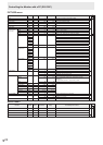
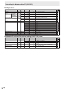
SCREEN menu
Function
Command Direction
Parameter Reply Control/Response contents *1
*2
(A) (B)
AUTO ASNC W 1 When the input mode is PC D-SUB, PC RGB.
-
○ ○
CLOCK CLCK WR 0-1200 0-1200 When the input mode is PC D-SUB, PC RGB.
Varies depending on the signal.
PHASE PHSE WR 0-63 0-63 When the input mode is PC D-SUB, PC RGB.
POSITIONING POSITION OF
THE LONGEST
DIRECTION
HPOS WR 0-100 0-100 0-800 on PC D-SUB, PC RGB.
Varies depending on the signal.
POSITION OF
THE SHORTEST
DIRECTION
VPOS WR 0-100 0-100 0-200 on PC D-SUB, PC RGB.
Varies depending on the signal.
SIZE POSITION OF
THE LONGEST
DIRECTION
HSIZ WR 0-100 0-100
POSITION OF
THE SHORTEST
DIRECTION
VSIZ WR 0-100 0-100
RESOLUTION
LONGEST
DIRECTION
RESOLUTION
HRES WR 300-1920 300-1920 When the input mode is PC D-SUB, PC RGB.
Only even numbers are valid for parameters.
Varies depending on the signal.
SHORTEST
DIRECTION
RESOLUTION
VRES WR 200-1200 200-1200
RESET ARST W 1
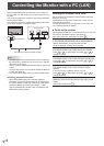
Controlling the Monitor with a PC (RS-232C)