


3
E
n
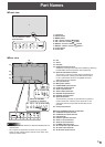
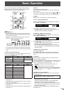
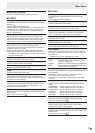
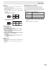
Front view
1
2345
6 7 8 9
The rear buttons if seen
from the front
1. LCD panel
2. INPUT button
3. MENU button
4. VOL -/Cursor control (
) button
5. VOL +/Cursor control (
) button
6. BRIGHT -/Cursor control (
) button
7. BRIGHT +/Cursor control (
) button
8. Power button
9. Power LED
Part Names
n
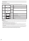
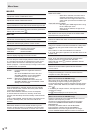
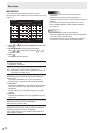
Rear view
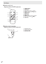
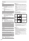
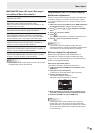
When the PN-ZB02
(optional) is attached
17
15
28272625 29
21 23
16
19
2018
22
24
13
14
32
3130 3433
10
12
11
9876 54 32
10. Fan
11. Vents
12. Handles
13. Expansion terminal cover
Additional input/output terminals are available by attaching
the PN-ZB02 interface expansion board (optional).
14. Optional attachment section
This section is used to connect optional hardware for
function expansion. Offering this attachment location
is not a guarantee that future compatible hardware
attachments will be released.
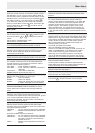
15. AC input terminal
16. Main power switch
17. PC/AV HDMI input terminal
18. PC D-sub input terminal
19. Audio input terminal
20. Audio output terminals
21. RS-232C output terminal
22. RS-232C input terminal
23. Optional terminal
This terminal is provided for possible future (optional)
function expansion. Offering of this terminal is not a
guarantee that future expanded functionality will be
provided.
24. Control kit terminal
When the PN-ZB02 (optional) is attached
25. PC/AV DVI-D input terminal
26. PC/AV DVI-D output terminal
27. LAN terminal
28. External speaker terminals
29. Audio 1 input terminals
30. Audio 2 input terminals
31. PC RGB input terminals
32. AV component input terminals
33. AV video input terminal
34. AV S-video input terminal
Caution
• Consult your SHARP dealer for attachment/detachment of
optional parts.
• Do not open the expansion terminal cover by yourself.
There are high voltage parts inside the cover which may
cause an electric shock.