


10
E
n
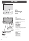
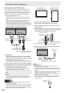
Front view
1
2345
6 7 8 9
The rear buttons if seen
from the front
1. LCD panel
2. INPUT button
3. MENU button
4. VOL -/Cursor control (
) button
5. VOL +/Cursor control (
) button
6. BRIGHT -/Cursor control (
) button
7. BRIGHT +/Cursor control (
) button
8. Power button
9. Power LED
Part Names
n
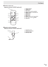
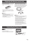
Rear view
17
15
28272625 29
21 23
16
19
2018
22
24
10
13
14
32
3130 3433
12
11
9876 54 32
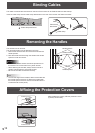
When the PN-ZB02
(optional) is attached
10
12
10
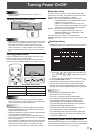
10. Fan/Fan cover
11. Vents
12. Handles
13. Expansion terminal cover
Additional input/output terminals are available by attaching
thePN-ZB02interfaceexpansionboard(optional).
14. Optional attachment section
This section is used to connect optional hardware for
function expansion. Offering this attachment location
is not a guarantee that future compatible hardware
attachments will be released.
15. AC input terminal
16. Main power switch
17. PC/AV HDMI input terminal
18. PC D-sub input terminal
19. Audio input terminal
20. Audio output terminals
21. RS-232C output terminal
22. RS-232C input terminal
23. Optional terminal
Thisterminalisprovidedforpossiblefuture(optional)
function expansion. Offering of this terminal is not a
guarantee that future expanded functionality will be
provided.
24. Control kit terminal
When the PN-ZB02 (optional) is attached
25. PC/AV DVI-D input terminal
26. PC/AV DVI-D output terminal
27. LAN terminal
28. External speaker terminals
29. Audio 1 input terminals
30. Audio 2 input terminals
31. PC RGB input terminals
32. AV component input terminals
33. AV video input terminal
34. AV S-video input terminal
Caution
• ConsultyourSHARPdealerforattachment/detachmentof
optional parts.
• Donotblockthefancover.
• Donotopentheexpansionterminalcoverbyyourself.
There are high voltage parts inside the cover which may
cause an electric shock.