


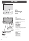

14
E
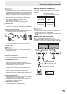
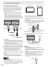
■ Connection with RS-232 cable
IfyouconnectthemonitorinadaisychainusingRS-232
cable,usingthemonitorbuttonsontheprimary(mainunit),
settingsarecopiedtothesecondary(expansionunit)and
operation from the primary can perform operation for all
monitors.SettingeachIDNo.inthemonitorisrequired.
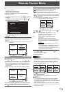
1. Connect the monitors in order.
Therstmonitorwillbesetasprimary(mainunit)andthe
secondmonitorandbeyondwillbesecondaries(expansion
units).
ConnecttheRS-232Coutputterminaloftherstmonitor
(primary)andtheRS-232Cinputterminalofthesecond
monitor(secondary)togetherusingRS-232cable(straight).
Connectinthesamewaytothethirdandsubsequentmonitors.
Upto25monitorscanbeconnected.(Dependingonthelength
ofthecableusedandthesurroundingenvironment.)
RS-232 straight cable
(commercially available)
First monitor: primary
Second monitor: secondary
Third monitor: connects to secondary
RS-232C input terminal
RS-232C
input terminal
RS-232C
output terminal
RS-232C
output terminal
2. Set the ID No.
Perform operation with the rear side buttons on the primary
monitor.IfyousetAUTOASSIGNIDNo.,locatedinthemenu
ofthemonitortoON,theIDNo.willbeautomaticallyassigned
inorderfromtheprimary.(Seepage24.)
(IfyouattachPN-ZR01thecontrolkit(optional),youcan
performoperationofthemonitorswiththeremotecontrolunit.)
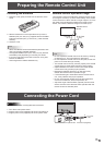
■ Connection with the control kit (optional)
If performing operation of the monitor with the remote control
unit,thePN-ZR01controlkit(optional)isrequired.
• Canperformoperationofanarbitrarymonitororall
monitorswiththeremotecontrolunitoftherstmonitor.
• Canperformoperationofupto25monitors.
• ConnectthemonitorstogetherinadaisychainwithRS-232
cable.
Attach the remote control sensor box as shown in the following
illustration.
* Whenattachedtotheleftside,becausethetopand
bottom for the remote control sensor box will be reversed
(theconnectioncablewillbeontop),therightsideis
recommended.
Caution
• Whenattachingtheremotecontrolsensorbox,turnthe
mainpowerswitchOFF.
• Exceptfortheremotecontrolsensorboxconnectioncable,
do not insert any other cable into the control kit terminal.
Also, do not connect any connection cables that have been
extended with commercially available cables.
For the monitor in
landscape orientation
For the monitor in
portrait orientation
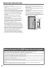
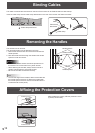
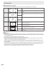
1. Insert the anti-rotation protrusion of the mounting
bracket into the anti-rotation hole of the monitor.
2. Secure the stand angling hole of the monitor with the
mounting screw.
3. Adjust the angle of the remote control sensor box, and
secure it with the xing screw, so that it may accurately
receive signals from the remote control unit.
Anti-rotation protrusion
Angle
adjustment
Anti-rotation hole
Mounting bracket
Mounting screw (short)
Fixing screw
Remote control
sensor box
Stand angling hole
4. Insert the remote control sensor box connection cable
into the control kit terminal.
Connection cableControl kit terminal
Remote control
sensor box
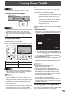
TIPS
• Whenyouconnecttheremotecontrolsensorbox,the
brightness sensor can be used.
The screen brightness will automatically change according
tolightingconditionsandthesurroundingbrightness.(See
page25.)
• Dependingonwhereithasbeenplacedorthesurrounding
conditions, the remote control sensor box may be
affected by the brightness of the main unit screen and the
brightness sensor may respond.
• Donotinstalltheremotecontrolsensorboxinextremely
bright or dark areas. The brightness sensor may not
function properly.
Brightness
sensor
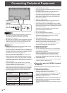
Connecting Peripheral Equipment