


2
XR-CA400/CA410
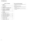
TABLE OF CONTENTS
1. GENERAL
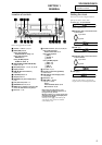
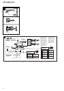
Location of Controls ....................................................... 3
Setting the Clock ............................................................. 3
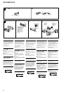
2. DISASSEMBLY ......................................................... 7
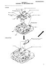
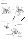
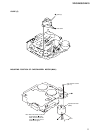
3. ASSEMBLY OF MECHANISM DECK........... 9
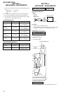
4. MECHANICAL ADJUSTMENTS ....................... 12
5. ELECTRICAL ADJUSTMENTS
Tape Deck Section .......................................................... 12
Tuner Section .................................................................. 12
6. DIAGRAMS
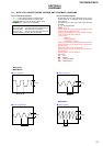
6-1. Note for Printed Wiring Boards and
Schematic Diagrams ....................................................... 13
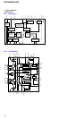
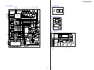
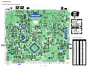
6-2. Printed Wiring Board – MAIN Board – ......................... 16
6-3. Schematic Diagram – MAIN Board (1/3) – ................... 17
6-4. Schematic Diagram – MAIN Board (2/3) – ................... 18
6-5. Schematic Diagram – MAIN Board (3/3) – ................... 19
6-6. Printed Wiring Board – KEY Board –............................ 20
6-7. Schematic Diagram – KEY Board – .............................. 21
6-8. IC Pin Function Description ........................................... 22
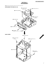
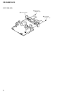
7. EXPLODED VIEWS ................................................ 24
8. ELECTRICAL PARTS LIST ............................... 27
Notes on chip component replacement
• Never reuse a disconnected chip component.
• Notice that the minus side of a tantalum capacitor may be dam-
aged by heat.
Flexible Circuit Board Repairing
• Keep the temperature of the soldering iron around 270 ˚C dur-
ing repairing.
• Do not touch the soldering iron on the same conductor of the
circuit board (within 3 times).
• Be careful not to apply force on the conductor when soldering
or unsoldering.