


– 5 –
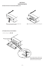
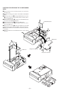
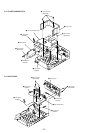
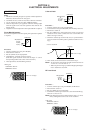
POSITIONS FOR SERVICING THE CONNECTOR
BOARD, SUB-TRANS BOARD, CHEMI-CON BOARD,
AND AMP BOARD
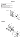
1 Remove the four screws securing the upper cover, and remove
the upper cover.
2 Remove the loading panel. (Refer to SECTION 3 DISASSEM-
BLY.)
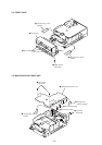
3 Remove the four screws A securing the MAIN board, five screws
B securing the rear panel, two flat cables (CN701, CN702),
and open the MAIN board as shown in the figure.
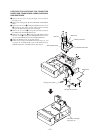
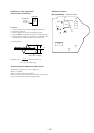
4 Remove the two screws C securing the heat sink, and remove
the AMP board and CHEMI-CON board.
5 Remove the two screws D securing the SUB-TRANS board
and four screws E securing the CONNECTOR board, and re-
move the SUB-TRANS board and CONNECTOR board.
6 Return the MAIN board to its original position.
7 Insulate these boards and the MAIN board with paper, etc., and
assemble the CONNECTOR board, SUB-TRANS board,
CHEMI-CON board, and AMP board on these boards.
Should be insulatable
with paper, etc.
A
A
C
D
B
B
E
Heat sink
SUB-TRANS board
AMP board
CHEMI-CON board
CONNECTOR board
MAIN boar
d
Flat type wire (CN701)
Flat type wire (CN702)