The TPA0103 Audio Power Amplifier Evaluation Module
3-5
Details
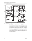
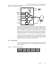
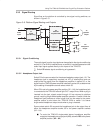
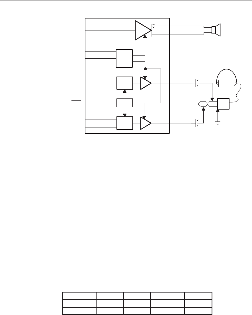
Figure 3–4. TPA0103 Amplifier IC
MODE A
MODE B
SHUTDOWN
CNTL
MUX
MUX
CNTL
L Line IN
L HP IN
R Line IN
R HP IN
C IN
C OUT+
C OUT–
R OUT+
L OUT+
TPA0103
HP/Line
The IC includes three separate amplifier channels: a left and right stereo pair
(single-ended) and a bridged-tied load (BTL) center channel. In the BTL mode,
the two output lines of the center channel operate 180° out-of-phase with each
other for increased power. The center channel speaker load is connected
directly across COUT+ and COUT–, and neither line is connected to ground.
BTL operation provides many benefits, including quadruple the output power
of single-ended operation and no need for bulky output coupling capacitors.
The left and right stereo channels operate in the single-ended mode, the
speaker load is connected between the OUT+ terminal through an output
coupling capacitor, to system ground. For more information, see the TPA0103
amplifier IC data sheet, TI Literature Number SLOS167.
3.2.2 Output Modes
The TPA0103 amplifier operates in any of three output modes or mutes
according to the status of the two control terminals MODE A and MODE B as
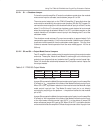
shown in Table 3–1.
Table 3–1. TPA0103 Output Modes
TERMINAL 3-Channel Mute Center Only L/R Only
MODE A L H L H
MODE B L L H H
Note: L = logic low, H = logic high


